As technology makes rapid strides in all spheres of everyday life, there arises the enduring demand for health-care and monitoring devices that are not only accurate, but also efficient.
Many of the bio-sensors and bio-devices today are implantable, which means that they are embedded inside the body of the subject. Understandably, then, arises the question of powering such devices. The answer: Wireless Charging.
Wireless Charging can be used to power a number of bio-sensors and other implantable aids such as:
- Pacemakers- These are used to control abnormal heart-beating rhythms. They are implanted in the chest or abdomen.
- Intracranial Pressure (ICP) Monitoring Devices- Essential to emergency situations such as brain injury, these are used to monitor the pressure inside the cerebro-spinal fluid and the brain tissue.
- Implantable Cardioverter Defibrillators- These are used to prevent sudden cardiac arrests in patients of ventricular fibrillation.
What effects will Wireless Charging have on these devices?
Wireless Charging would improve the life of the device, thereby reducing the need for replacing the existing device, which not only poses a risk due to surgery, but also creates additional bio-waste. Keeping the battery of the device fully charged would also result in an increased efficiency of the device.
What do we do here?
Here, we study Wireless Charging of Pacemakers. Imagine having only to place a block on your chest, and have your heart beat hard again!
How a Pacemaker WorksWe deal with a Demand Pacemaker, which provides electrical heart-stimulating pulses only in the absence of natural heartbeat. When it was introduced in 1964, the Demand Pacemaker offered significant advantage over the previously-used pacing devices, which delivered a fixed-rate pulse, thus competing with natural heartbeat and sometimes inducing ventricular fibrillation. The Demand Pacemaker also prolongs battery life because it is only activated when pacing stimuli are needed.
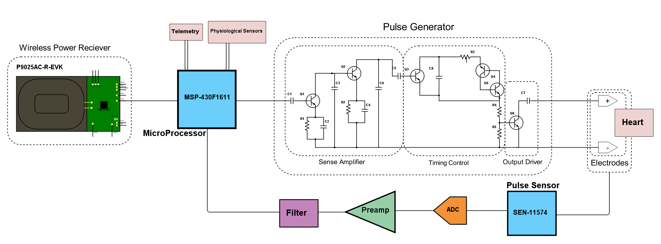
The Demand Pacemaker, connected to the IDT Wireless Power Receiver Board P9025AC-R-EVK, is shown in Schematic Form.
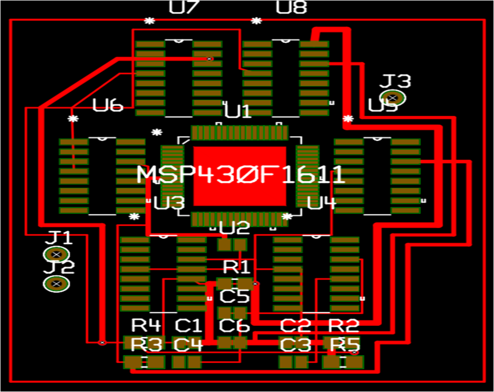
The Pacemaker's PCB Layout is shown.
Note that junctions J1 and J2 connect to the terminals of the P9025AC-R-EVK Receiver board, while the junction J3 leads to the electrodes implanted in the heart.
The Sense Amplifier amplifies and normalizes the cardiac signal. It lets out undesired signals like the P and T waves and 60 Hz stray signals. Q1 and Q2 are Class A amplifiers. AC signals at the collector of Q2 are coupled with capacitor C8 to momentarily turn on Q3, which is the Timing Capcitor (C8) discharge switch.
The Sense Amplifier incorporates a bandpass filter with a bandwidth of 20-30 Hz that limits the low frequency response of the detecting circuit to discriminate against the P and T waves and any other frequencies below 20 Hz.
When the Pacemaker is required to operate in demand mode, each pulse transmitted through capacitor C5 to the base of transistor Q3 causes the transistor to conduct. Capacitor C8 discharges through the collector–emitter circuit of the transistor. In this case, the timing cycle is interrupted and the junction of capacitor C8 and resistor R3 does not increase in potential to the point where transistors Q4 and Q5 are triggered to conduction. After capacitor C8 discharges through transistor Q3, the transistor turns off. The capacitor then starts charging once again and the new cycle begins immediately after the occurrence of the last heartbeat.
Making a Pacemaker WirelessSince a Pacemaker is not easily available (a condemned machine is officially a bio-hazard) and is fairly expensive, we recreate here the most integral component of a Pacemaker: its Pulse Generating Circuit.
A pulse generating circuit has to deliver electrical pulses at regular intervals of time. Such a circuit can be created as follows.
Step 1: Ready your Supplies!
What you'll need for this is an NE 555 made by Texas Instruments, an LED bulb, a 0.01 μF Capacitor, a 10 μF Capacitor, a 330 Ω Resistor, a 270 kΩ Resistor, a 33 kΩ Resistor, a breadboard and plenty of jumper wires. You'll also need a power source, which includes the IDT P9038-R-EVK - Qi 5W Transmitter and the IDT P9025AC-R-EVK - Qi 5W Receiver.
Step 2: Ready the Working Circuit
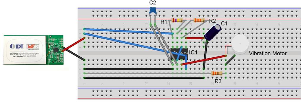
Connect the NE 555 to the breadboard. Note the orientation of the small IC using the notch at the top.
(A) NE 555 IC and Receiver Board
Connect the Receiver board's OUT point to the NE 555's Power (8) and Reset (4) pins. Connect the Receiver's GND- terminal to the NE 555's Ground (1). Now connect the 0.01 μF Capacitor between the Ground (1) and Trigger (2) pins of the NE 555. This helps in regulating power flow into the IC and the initiation of the circuit.
(B) Resistors
Now connect the 270 kΩ Resistor between the +VCC (8) and Discharge (7) pins and the 33 kΩ Resistor between the Discharge (7) and Threshold (6) pins. Since I only had 90 kΩ and 22 kΩ resistors, I connected 3 90 kΩ resistors in series and a parallel combination of two 22 kΩ resistors in series with another 22 kΩ resistor to get the desired resistances.
(C) Capacitor
Next take the 10 μF capacitor; connect its positive terminal to the NE 555's Control Voltage (5) point and its negative terminal to the power sources ground terminal.
(D) LED Bulb
On this connection, attach a 330 Ω resistor which is connected to the negative terminal of the LED bulb. Connect the bulb's positive terminal to the NE 555's Output (3) pin.
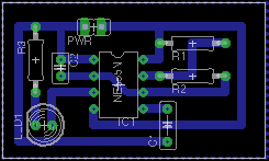
The PCB design of the Pulse Generating Circuit is shown for reference.
Note that the magnitudes (values) of C1, R1 and R2 need to be chosen according to the time period of periodicity of the pulse (or equivalently its frequency). Get a conversion chart here.
Step 3: Ready the Powering Mechanism
Now get hold of the amazing Transmitter Board, and plug it in through its Mini USB. As current flutters in through its coil, a green and a red light should come to life atop the board. Now take the Receiver Board close to the Transmitter. At the correct relative orientation of and distance between the two boards, an induction current would be set on in the Receiver's coil, thereby lighting an LED on board. To test this or learn more, see this. Note that the green light on the Transmitter begins to blink and the red light goes off. Phew!
Your LED in the pulsating circuit should now begin to blink.
A device that closely matches the functioning of a pacemaker and heart is a vibration motor, which can be operated using the Pulse Generating Circuit in place of the LED.
The SparkFun Vibration Motor used here vibrates periodically with a time period of 2 seconds given the resistances and capacitance used.
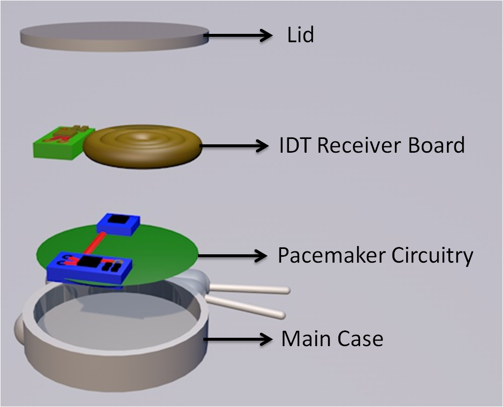
Packing the PacemakerThe Pacemaker is enclosed in a hermetically sealed case. A 3-D Model of the Pacemaker and how the various components fit in is given below.
Earlier, the pacemaker needed to be replaced surgically when the battery run out. With this project, the painstaking and risky process is no longer required!
TestingIn order to test the working of the system, take the Pulse Generator (with LED) and fasten it inside your shirt. Make sure to keep the back side of the Receiver board PCB away from the body. If the board is kept the other way around, then the insulating sticker on top of the receiver coil would prevent any induction from occurring.
Now connect the Transmitter board to a power source and bring it close to the circuit. Recall the correct orientation of the two coils that we had studied earlier. When the coils are placed correctly, the LED should blink.
Inductive Charging is indeed a boon for implantable bio-devices, since it can pave the way for a plethora of devices, with makers no longer worried about battery life!




_3u05Tpwasz.png?auto=compress%2Cformat&w=40&h=40&fit=fillmax&bg=fff&dpr=2)


Comments
Please log in or sign up to comment.