


Hardware components | ||||||
| × | 2 | ||||
 |
| × | 2 | |||
 |
| × | 1 | |||
 |
| × | 1 | |||
| × | 1 | ||||
Software apps and online services | ||||||
 |
| |||||
| ||||||
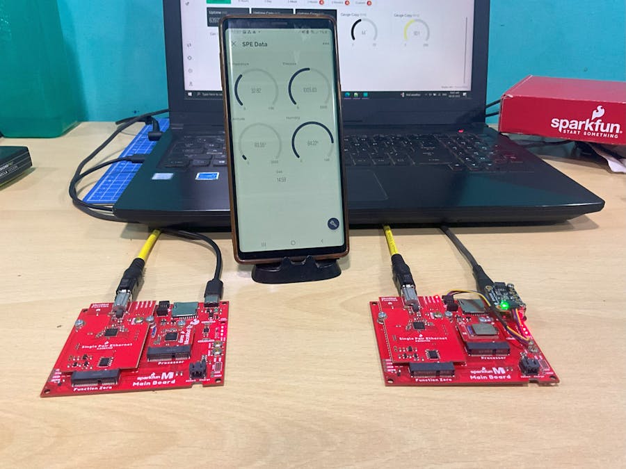
For my SparkFun SPE contest entry, I designed a real-time lab monitor that measures temperature, humidity, and gas levels using the BME688 sensor. The sensor data is transmitted to an ESP32 microcontroller using the SPE (Single PAir Ethernet) data transmission module. The ESP32 then logs the sensor readings and sends them to a server where the data can be viewed on a dashboard.
The key components used in this project are:
- Bosch BME688 sensor - Measures temperature, humidity, and gas (VOC) levels
- MicroMod Main Board - Connects the BME688 sensor
- ADIN1110 Function Board - Enables wireless data transmission using SPE
- ESP32 microcontroller - Receives sensor data over SPE and sends it to the server
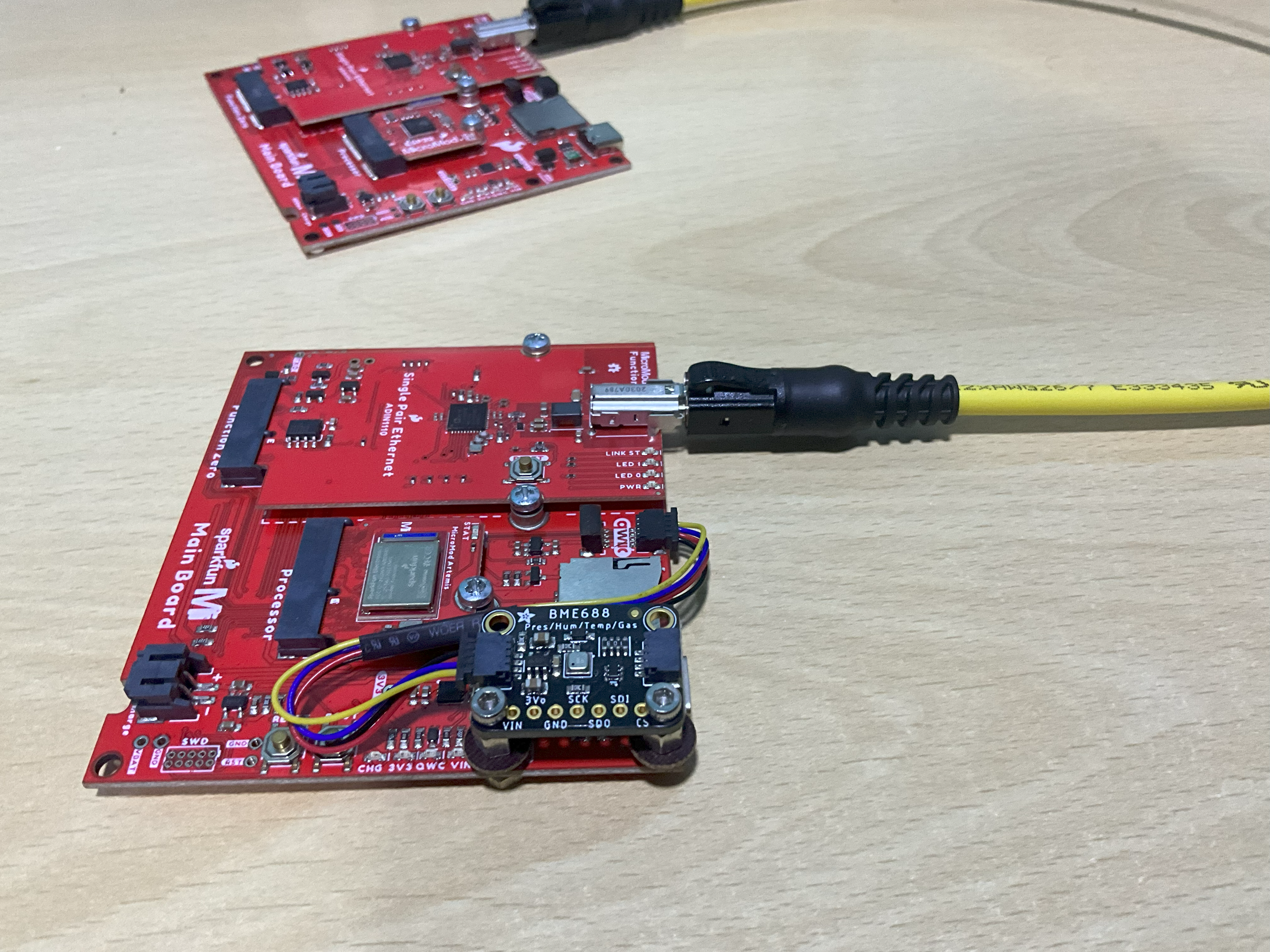
The BME688 sensor is connected to the MicroMod Main Board which reads the sensor measurements. The Main Board is then connected to the ADIN1110 Function Board which facilitates data transmission using the SPE protocol.
The SparkFun MicroMod Single Pair Ethernet Function Board utilizes the Analog Devices ADIN1110 Ethernet transceiver chip. It introduces the 10Base-T1L Single Pair Ethernet protocol to the MicroMod ecosystem, enabling prototyping of long-range 10Mb/s Ethernet connections over single-pair copper wire of up to 1km in length. The board supports the 802.3cg standard and is compatible with the MicroMod Single Pair Ethernet Kit which provides most components needed for development.
On the receiving end, an ESP32 microcontroller is paired with the transmitting ADIN1110 board. The ESP32 receives the live sensor readings transmitted over SPE. It then logs this data and sends it to a web server via WiFi.
The sensor measurements can now be visualized on a dashboard interface in real-time. This allows remote monitoring of lab conditions for safety and efficiency purposes.
Build ProcessThe BME688 sensor, MicroMod Main Board and ADIN1110 Function Board were mounted together as shown in the wiring diagram.
An ESP32 development board was used to receive the sensor data over SPE. The ADIN1110 was programmed to transmit data packets containing the sensor readings every second using the SparkFun code library.
Connect the Adafruit BME688 environmental sensor to the QWIIC connector of the Transmitter board.
Connect the 0.5m SPE cable to the Single Pair Ethernet ADIN1110 modules as shown
Now the hardware is ready to test.
Setting up the Blynk DashboardOpen your Arduino IDE and navigate to "Sketch" > "Include Library" > "Manage Libraries." Search for and install the following libraries:
- Blynk
- WiFiManager
Sign up for a Blynk account or log in if you already have one. Create a new project and choose the ESP32 as your device. I've named my project "SPE Data"
You'll receive an authentication token via email. Keep this token handy; you'll need it in the code.
Create virtual pins in the datastreams for the Dashboard as shown below.
Copy and paste the following Arduino sketch into your Arduino IDE. Replace <YourAuthToken> with the authentication token you received via email.
#include <Arduino.h>
#include <WiFiManager.h>
#include <BlynkSimpleEsp32.h>

// Replace with your network credentials
char ssid[] = "YourSSID";
char pass[] = "YourPassword";

// Replace with your Blynk authentication token
char auth[] = "YourAuthToken";

void setup() {
  // Initialize Serial Monitor
  Serial.begin(115200);

  // Initialize WiFiManager
  WiFiManager wifiManager;

  // Uncomment the next line if you want to reset Wi-Fi settings
  // wifiManager.resetSettings();

  // Connect to Wi-Fi
  if (!wifiManager.autoConnect("ESP32-AP")) {
    Serial.println("Failed to connect to Wi-Fi, restarting...");
    ESP.restart();
  }

  // Initialize Blynk
  Blynk.begin(auth, ssid, pass);
}

void loop() {
  Blynk.run();
}Download the SparkFun ADIN1110 Arduino Library for the ADIN1110 Function Boards. Follow the instructions to set up the Micromod processors for the Mainboard.
MicroMod Artemis Processor Board Hookup Guide - SparkFun Learn
MicroMod ESP32 Processor Board Hookup Guide - SparkFun Learn
Transmitter Code:
Includes SparkFun_ADIN1110_Library.h for ADIN1110 functionality. Configures ADIN1110 as the transmitter on the desired channel. Sets data packet payload to sensor readings. Transmits packets every 1 second
#include "SparkFun_SinglePairEthernet.h"
#include <Arduino_JSON.h>
#include <Wire.h>
#include <SPI.h>
#include <Adafruit_Sensor.h>
#include "Adafruit_BME680.h"
SinglePairEthernet adin1110;
#define BME_SCK 13
#define BME_MISO 12
#define BME_MOSI 11
#define BME_CS 10
#define SEALEVELPRESSURE_HPA (1013.25)
Adafruit_BME680 bme;  // I2C
JSONVar lastBMEData;
unsigned long last_report;
unsigned long last_toggle;
int sample_data_num = 0;
byte deviceMAC[6] = { 0x00, 0xE0, 0x22, 0xFE, 0xDA, 0xC9 };
byte destinationMAC[6] = { 0x00, 0xE0, 0x22, 0xFE, 0xDA, 0xCA };
void setup() {
Serial.begin(115200);
while (!Serial)
;
Serial.println("Single Pair Ethernet - Sensor data");
/* Start up adin1110 */
if (!adin1110.begin(deviceMAC)) {
Serial.print("Failed to connect to ADIN1110 MACPHY. Make sure board is connected and pins are defined for target.");
while (1)
;  //If we can't connect just stop here
}
Serial.println("Configured ADIN1110 MACPHY");
/* Wait for link to be established */
Serial.println("Device Configured, waiting for connection...");
while (adin1110.getLinkStatus() != true)
;
while (bme.begin() == false)  //Begin communication over I2C
{
char msg[] = "The BME280 sensor did not respond. Please check wiring.";
adin1110.sendData((byte *)msg, sizeof(msg));
delay(1000);  //Freeze
}
// Set up oversampling and filter initialization
bme.setTemperatureOversampling(BME680_OS_8X);
bme.setHumidityOversampling(BME680_OS_2X);
bme.setPressureOversampling(BME680_OS_4X);
bme.setIIRFilterSize(BME680_FILTER_SIZE_3);
bme.setGasHeater(320, 150);  // 320*C for 150 ms
}
#define diff(a, b, max_diff) ((a >= b + max_diff) || (a <= b - max_diff))
void loop() {
unsigned long now;
bool force_report = false;
//Collect the BME sensor data in an object
if (!bme.performReading()) {
Serial.println("Failed to perform reading :(");
return;
}
JSONVar BMEData;
BMEData["humidity"] = bme.humidity;
BMEData["pressure"] = bme.pressure / 100.0;
BMEData["alt"] = bme.readAltitude(SEALEVELPRESSURE_HPA);
BMEData["temp"] = bme.temperature;
BMEData["gas"] = bme.gas_resistance / 1000.0;
//If any sensors have significantly changed, send a new report right away
if (diff((double)BMEData["humidity"], (double)lastBMEData["humidity"], 2) || diff((double)BMEData["pressure"], (double)lastBMEData["pressure"], 300) || diff((double)BMEData["alt"], (double)lastBMEData["alt"], 30) || diff((double)BMEData["temp"], (double)lastBMEData["temp"], 1)) {
force_report = true;
}
now = millis();
if (now - last_report >= 5000 || force_report) {
if (adin1110.getLinkStatus()) {
String jsonString = JSON.stringify(BMEData);
adin1110.sendData((byte *)jsonString.c_str(), strlen(jsonString.c_str()) + 1);
Serial.print("Sent (");
Serial.print(strlen(jsonString.c_str()));
Serial.print(") bytes :\t");
Serial.println(jsonString.c_str());
lastBMEData = BMEData;
last_report = now;
} else {
Serial.println("Waiting for link to resume sending");
}
}
now = millis();
if (now - last_toggle >= 1000) {
digitalWrite(LED_BUILTIN, !digitalRead(LED_BUILTIN));
last_toggle = now;
}
delay(100);
}
Receiver Code:
Includes SPE_Arduino_Library.h for SPE protocol. Sets ESP32 as receiver paired to the transmitter. Initializes WiFi and ThingSpeak credentials. Waits for data packets in the main loop. Extracts sensor values from the payload on reception. Logs and uploads data to the server. Manages error handling.
#include "SparkFun_SinglePairEthernet.h"
#include <Arduino_JSON.h>
#define BLYNK_PRINT Serial
/* Fill in information from Blynk Device Info here */
#define BLYNK_TEMPLATE_ID ""
#define BLYNK_TEMPLATE_NAME ""
#define BLYNK_AUTH_TOKEN ""
#include <WiFi.h>
#include <WiFiClient.h>
#include <BlynkSimpleEsp32.h>
BlynkTimer timer;
SinglePairEthernet adin1110;
const int MAX_CHARS_DISPLAY = 4 * 20;
//C string to hold entire display text + a Null terminator
char display_text[MAX_CHARS_DISPLAY + 1];
char display_updated = false;
unsigned long lastBlink = 0;
byte deviceMAC[6] = { 0x00, 0xE0, 0x22, 0xFE, 0xDA, 0xCA };
// Set password to "" for open networks.
char ssid[] = "";
char pass[] = "";
float temperature, humidity, pressure, gas, altitude;
static void rxCallback(byte *data, int dataLen, byte *senderMAC) {
JSONVar BMEData = JSON.parse((char *)data);
memset(display_text, '\0', MAX_CHARS_DISPLAY + 1);
temperature = (double)BMEData[temperature];
humidity = (double)BMEData[humidity];
pressure = (double)BMEData[pressure];
gas = (double)BMEData[gas];
altitude = (double)BMEData[altitude];
Blynk.virtualWrite(V10, temperature);            // Send temperature to V11
Blynk.virtualWrite(V12, humidity);               // Send humidity to V12
Blynk.virtualWrite(V11, pressure);               // Send pressure to V13
Blynk.virtualWrite(V13, gas);                    // Send CO2 level to V14
Blynk.virtualWrite(V14, altitude);               // Send altitude to V15
Blynk.virtualWrite(V6, "SPE Design Challenge");  // Send altitude to V15
display_updated = true;
}
void myTimerEvent() {
// You can send any value at any time.
// Please don't send more that 10 values per second.
Blynk.virtualWrite(V5, millis() / 1000);
}
void linkCallback(bool linkStatus) {
memset(display_text, '\0', MAX_CHARS_DISPLAY + 1);
strncpy(display_text, (linkStatus) ? "\r\nConnected" : "Disconnected", MAX_CHARS_DISPLAY);
display_updated = true;
}
void setup() {
Serial.begin(115200);
while (!Serial)
;
Serial.println("Single Pair Ethernet - Receiver");
Blynk.begin(BLYNK_AUTH_TOKEN, ssid, pass);
// Setup a function to be called every second
timer.setInterval(1000L, myTimerEvent);
/* Start up adin1110 */
if (!adin1110.begin(deviceMAC)) {
Serial.print("Failed to connect to ADIN1110 MACPHY. Make sure board is connected and pins are defined for target.");
while (1)
;  //If we can't connect just stop here
}
Serial.println("Connected to ADIN1110 MACPHY");
/* Set up callback, to control what we do when data is recieved and when link changed*/
adin1110.setRxCallback(rxCallback);
adin1110.setLinkCallback(linkCallback);
/* Wait for link to be established */
Serial.print("Waiting for\nconnection...");
while (adin1110.getLinkStatus() != true)
;
}
void loop() {
Blynk.run();
timer.run();  // Initiates BlynkTimer
unsigned long now = millis();
if (now - lastBlink >= 1000) {
digitalWrite(LED_BUILTIN, !digitalRead(LED_BUILTIN));
}
delay(5);
}
On the ESP32, Arduino code was written to initialize it as an SPE receiver and pair it with the transmitter. The ESP32 code contains functions to decode the received data packets and extract the sensor values. It then logs these readings to the Serial Monitor and uploads them to a server hosted on ThingSpeak using WiFi. The ThingSpeak dashboard displays live graphs of the temperature, humidity and gas levels for remote monitoring.
In your Blynk app, add various widgets like buttons, sliders, and displays to your project dashboard. Assign the widgets to the appropriate virtual pins (e.g., V1, V2, V3) in the app. Use the virtual pins in your Arduino sketch to control and monitor your ESP32's GPIO pins.
Project DemoThis approach allowed me to effectively transmit live sensor measurements wirelessly and access them remotely on a dashboard for lab monitoring.
Dashboard
Testing the project
Careful temperature and gas level regulation in laboratories is crucial for reducing energy waste. This project helps achieve that by providing live monitoring and analysis of critical parameters. Some key sustainability benefits are:
- Optimized HVAC control saves on electricity costs by precisely maintaining optimal conditions
- Early leak detection prevents the emission of greenhouse gases into the atmosphere
- Remote monitoring eliminates the need for frequent on-site checks, cutting down travel emissions
- Automatic alerts assist in proactive issue resolution before problems escalate
By making labs more efficient to operate, this technology plays a small role in minimizing our environmental footprint and contributing to a greener future.
Challenges & Lessons Learned - Troubleshooting1. On checking the forum, many developers faced this issue on the SPE kit.
Expressing gratitude to SparkFun for inspiring the project and community.
Let me know if you need any section expanded upon or have additional questions! I aimed to cover the key areas SparkFun evaluates for the submission. Please provide feedback on how I can improve the blog post.


_3u05Tpwasz.png?auto=compress%2Cformat&w=40&h=40&fit=fillmax&bg=fff&dpr=2)
Comments
Please log in or sign up to comment.