Welcome again to this Amburo tutorial, in line with the previous tutorials of this series I will be delivering this last part, which is cloning radio signals. The same as the infra-red cloning, I suggest you take a look at the original publication.
Radio Cloning As you will see it has the very basics but a good starting point.
In this tutorial, I will show you a script that is able to clone and emit. It has the same concept as the infra-red code: poner link an infrared. In fact, you will see that the code is pretty similar. Without further ado, let's get started.
Supplies:We will use an Arduino board, a few cables, and of course, a 433Mhz radio receiver and emitter boars. Bear in mind you can use other frequencies as well but that will depend on the device you want to clone.
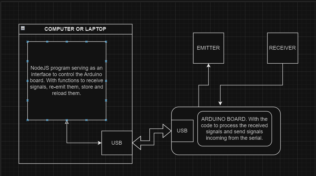
As you can see I use this way of connecting the boards. I have to mention, that I have seen other ways of connecting them but for me, this way works perfectly. The receptor is connected to 3.3v and to the analog A0. And the emitter to 5v and the digital pin 4.
As you can see, at the top of our script, you will find the definition of the variables we will be using to configure the behavior of the cloning and emitting. The loop part will be expecting 1 or 2 in order to clone or emit.
The waitAndClone function will be in charge of reading A0 until it flushes and stores the HIGH and LOW states of the signals into signals array. To be super honest I cannot explain much about the values of the Thresholds, maxSignalLength, or timeDelay since they are the product of trial and error. They worked for me on many RF devices. I don't discard you may need to fine-tune them to make it work for a specific device. For example:
const int timeDelay = 105; //slow down the signal transmission (can be from 75 - 135) 105
readSignalsFromSerial function has no mystery, it reads the string incoming from the serial and stores it in signals array in order to be ready for later execution. You will notice this function is the same for the code of infra-red cloning.
Finally, sendSignal function sends the signal stored in signals array by looping it and delegating the turning on and off to sendRadioSignalSingleCommand function.
As mentioned, this sketch follows the same logic as its ancestor infra-red. read the signals, store them in an array, receive the signal, and emit it. The only variation is in how the signal is interpreted. In this case in each element of the array, we store alternatively the low and high states of the sensor as time value. dar un ejemplo
My Shield:As I did with the infra-red tutorial, I will test this with the shield I made using the slots for the radio boards. You will have to attach the boards with cables. Is not that bad you may have to handle them with care at the moment of pointing the Led to de desired device.
Taking advantage of the interface we created in the previous tutorial. And since the input and output of the radio cloner/emitter sketch follow the same pattern as the infra-red one: WAITING_4_SIGNAL, READING_SERIAL signaling the board is ready to clone or receive the signal sequence from the serial or 1/2 for activating the board cloning and emitting. We are going to use this same interface to control the board, it will let us clone, emit, save, and retrieve signals from different radio devices.
Diagram:As you may know, nowadays radio devices work with ciphered communication, which basically means that is not possible to intercept and clone the signal between the emitter and receiver. In some cases, the signaling is different in each interaction and the signal can not be repeated. You may be able to intercept the signals but even though you can repeat it, the receptor will not accept it. This makes this kind of device more secure. In other cases, some devices will establish a communication back and forth like a conversation in order to activate, open, or whatever the device does. Of course, to achieve this you will need more complexity in the code if you want to keep using this kind of board, or more technology, like for instance using modern radio boards, like the hc-12 module or the nrf24l01 module. So in the future, I will be exploring these new strategies and technologies to create a new series of tutorials.
But for a starting point, and, why not, automate one or two lights or whatever you want to control This sketch will come in very handy.
See you in the next one and have a good one.


_ztBMuBhMHo.jpg?auto=compress%2Cformat&w=48&h=48&fit=fill&bg=ffffff)


Comments
Please log in or sign up to comment.