


Hardware components | ||||||
| × | 1 | ||||
 |
| × | 1 | |||
| × | 1 | ||||
| × | 1 | ||||
| × | 1 | ||||
| × | 1 | ||||
| × | 1 | ||||
| × | 1 | ||||
| × | 1 | ||||
| × | 1 | ||||
Software apps and online services | ||||||
| ||||||
| ||||||
 |
| |||||
 |
| |||||
 |
| |||||
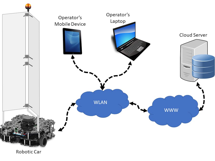
The Autonomous UV Wiper is an open source design system for an Ultraviolet Germicidal Irradiation (UVGI) robot that includes job data storage in the cloud and remote wireless mobile device monitoring and control. The system is composed of a differential-drive Robotic Car that uses ultraviolet (UV) light for room disinfection, a Cloud Server for storing the sanitizing job data and an Android mobile application for remotely monitoring and controlling the sanitizing job at hand. The Robotic Car carries a UV light set mounted on top of it and navigates autonomously the room applying the UV light to all exposed surfaces inside the room, killing bacteria and viruses, particularly the SARS-CoV-2 virus.
During the sanitizing process, the Robotic Car automatically builds a map for the room being sanitized, which is shown in real-time along with the area covered already by the UV light. It is also capable of detecting living beings (people and animals) by using artificial intelligence powered computer vision. If any living being is detected, it automatically turns off the UV light as a safety measure and provides visual and audible alarms to the operator.
During the sanitizing job, the Robotic Car automatically connects to the Cloud Server and sends every few seconds the room’s map being built, along with a graphical representation of the area currently exposed to the UV light radiation and a picture of the room angle currently observed by the Robotic Car's camera. The Cloud Server receives these data and stores them in a database; it also provides a web page with a graphical interface from where users can access and monitor the sanitizing job in real-time.
A custom Android application developed for the operator's use displays the same data provided by the Cloud Server at their web interface and also displays in real-time the live video stream from the Robotic Car’s camera. This allows the operator to be fully aware of what’s currently seeing the Robotic Car inside the room, as an extra safety measure. The Android application also allows the operator to remotely activate/deactivate the Robotic Car and manually command it to certain spots inside the room, for instance to cover certain areas the Robotic Car could not properly reach for any reason.
MAIN SPECIFICATIONS- The robot uses computer vision to detect living beings (people and animals). It immediately turns off the UV light if any is detected. Because it’s fully autonomous, it doesn't require the presence of the operator inside the room being radiated. The operator uses a mobile device to remotely monitor and control the robot’s operation (that is, from the outside of the room) and she has also access to the robot’s camera live video feed in the mobile device.
- For safety reasons, the robot applies radiation just in a horizontal field of view of 52 degrees, 10 degrees less that its camera field of view, which is 62 degrees (safety margin for the computer vision detection). On the other hand, the radiation vertical field of view is 49 degrees which is the same as the camera (there's no need of a 10-degree safety margin). Because the robot has differential-drive configuration, it can rotate in place for a 360-degree coverage and movement.
- The robot stores data for each sanitizing job, including the UV light lamp life. The Robotic Car battery has a battery life of more than 2 hours and the UV-light subsystem’s battery life is 2 hours as well. Both batteries are Lithium-polymer, they are easily swappable and can be charged in about 2-3 hours. One or more backup battery sets can be carried with with the Robotic Car for longer work periods.
- The Robotic Car’s size is 281x306x1600 (LxWxH, mm). It can deliver a kill dose of 25.5mJ/cm^2 at 1 meter (3.75 feet) in 2.8 minutes.
- The Robotic Car mostly uses modular hardware parts readily available. The UV light stand and reflector can be easily manufactured. All the software for mapping, autonomous navigation and computer vision is also readily available. The path planning, UV light subsystem control, Cloud Server software and Android application are in process of being developed. 70% of them are already completed.
- The Bill of Materials (BOM) total less than 1, 900 USD.
- The hardware design uses an already developed and widely commercialized robotic car platform (the ROBOTIS TurtleBot3 Waffle Pi); it has all the software required to operate and support of the manufacturer. On the other hand, the UV light subsystem uses very common and readily available parts and is easy to manufacture. Those reasons make the manufacturing process and the maintenance this system's UV radiation applying Robotic Car very simple. It doesn't require a highly skilled workforce to manufacture and repair.
Figure 1 shows the system block diagram comprising the three main parts: the Robotic Car for applying the UV radiation, the Cloud Server that stores detailed data from each sanitizing job, which can be accessed from a PC or mobile device, and the Android application for the operator that can run on a cell phone or tablet.
To perform a sanitizing job, a trained system operator places the Robotic Car inside the room to sanitize, powers up the Robotic Car and closes the door behind. Once the door is closed, it uses a mobile device (cell phone or tablet) and the custom Android application to send a start signal to the Robotic Car, so it can begin the sanitizing job. From then on, the system operator can monitor in real-time the sanitizing job data uploaded by the Robotic Car. She can monitor the sanitizing job by using the mobile device or by accessing the Cloud Server's web site. A sanitizing job data comprises the room map being built in real-time, the Robotic Car’s followed path, the total room area covered by the UV light, the job time, battery life time, system errors and warnings, etc. Figure 2 shows a sketch of the web page for a sanitizing job and Figure 3 shows a sketch of the Android application's graphical user interface.
To upload data to the Cloud Server, the Robotic Car accesses the Internet through a Wi-Fi hot spot provided by the mobile device, which has to have a 3G/4G LTE link. On the other hand, the Robotic Car runs a software module that makes it a live video server over the Wi-Fi network. The Android application connects to this server to show the live video feed from the Robotic Car's camera in its graphical user interface (see Figure 3.b).
If for some reason the Robotic Car gets stuck, it will turn off the UV light, send a warning signal to the Cloud Server (which is automatically reflected at the web interface and the Android application’s graphical interface) and do up to three maneuvers to unblock itself. If that fails, it will get into a ‘resting’ state and send an error alarm to the Cloud Server and the operator’s mobile application, so it can be manually unblocked. Then, it can resume operation to finish the current sanitizing job.
The Robotic Car uses a LIDAR sensor to map and localize itself in the room and a camera to detect living beings (people and animals) by using computer vision. It has a built-in mechanism to immediately deactivate the UV light if it detects people or animals inside the room. Because the camera has a relatively narrow field of view (58 degrees), the UV light is applied in a horizontal radiation pattern of 48 degrees, 10 degrees less than the camera’s field of view. It will only apply UV radiation to anything in front of it that can be seen in the camera image (with a 10-degree error margin for reliably detecting living beings at the image's left and right edges), to avoid shedding the UV light over people or animals.
HARDWARE BLOCK DIAGRAMFigure 4 shows the hardware block diagram for the Robotic Car. To make the system easily to manufacture and low-cost, I’m basing it on the TurtleBot3 Waffle Pi development platform developed and manufactured by ROBOTIS Inc. (see Figure 5), which is very affordable and has all the most important hardware for the Robotic Car, including the mobile platform, a LIDAR sensor, an RGB camera and a Raspberry Pi board as a control computer, which includes Wi-Fi for connecting with the Cloud Server. The TurtleBot3 design is fully open source hardware, which allows future modifications for future improvements.
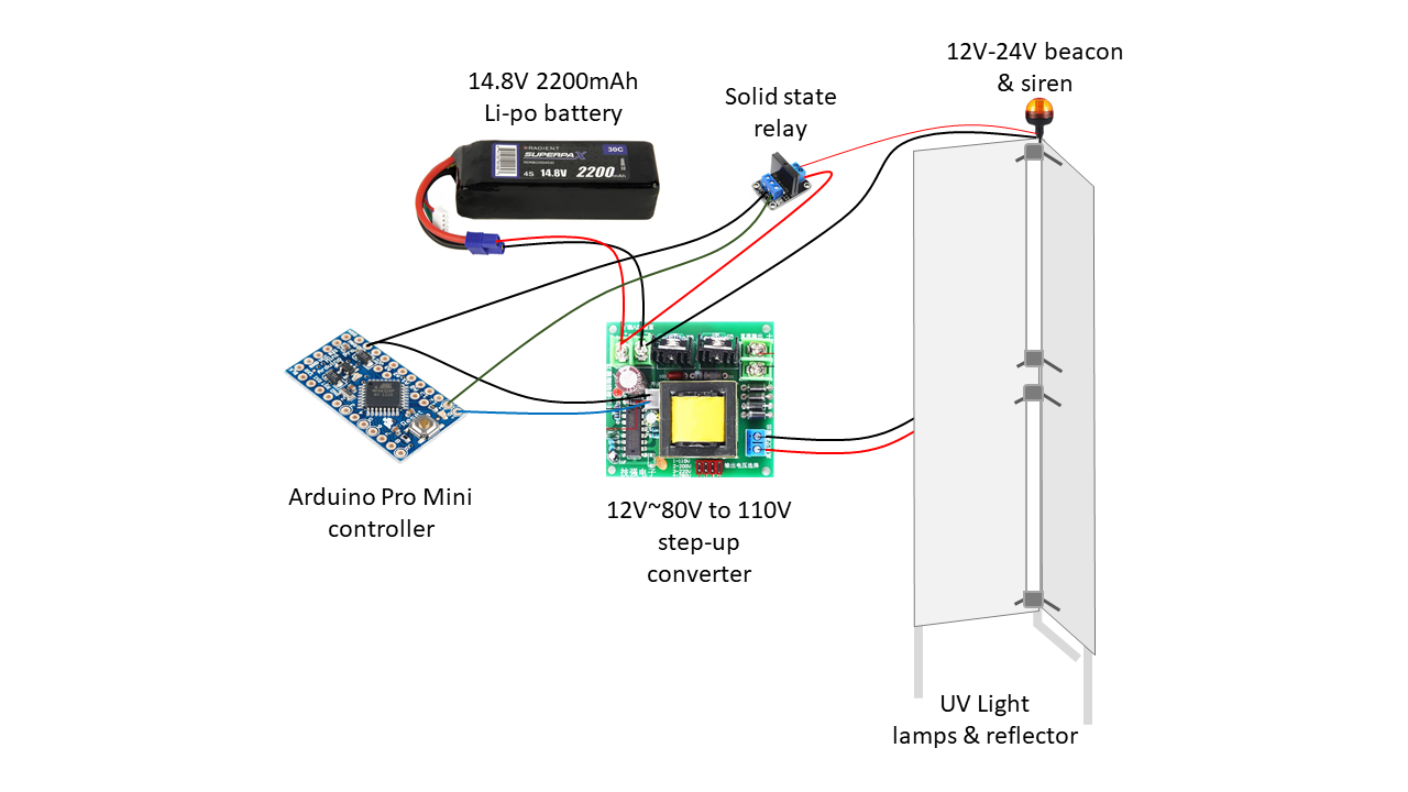
To the TurtleBot3 Waffle Pi, I added the UV light subsystem (See Figure 6) composed by two 30-What UV lamps inside a reflector with a 48 angle coverage, an Arduino Pro Mini as the subsystem’s controller and a dedicated Li-Po battery. The UV light subsystem is a fully open source hardware custom design. Figure 7 shows the complete UV radiation applying Robotic Car.
The Robotic Car software comprises modules in the following categories:
- ROS nodes provided by ROBOTIS INC., the manufacturer of TurtleBot3 Waffle Pi, which allows the platform operation with its main sensors (LIDAR and camera) and includes nodes for SLAM and AMCL navigation. All this software is fully open source.
- Other readily available ROS nodes. For instance, I am using the ‘web_video_server’ node to stream live video from the Robotic Car to the Android application (through a Wi-Fi hots pot provided by the mobile application). This ROS node is open source as well.
- ROS custom nodes being specifically developed for this project (fully open source, as well):
- ‘Random Walk’ path planning algorithm ROS node: to make the Robotic Car randomly navigate the room while maps and sanitizes it.
- ‘Go-to-goal’ ROS node: to manually drive the Robotic Car to a given pose by clicking or tapping a pose over the web interface’s room map in a web browser or the Android application.
- Computer vision living being detection: to detect people and animals in the room.
- UV light subsystem ROS node: to control the UV light subsystem.
- HTTP communications ROS node: to send receive data to/from the Cloud Server.
Here’s what each of our custom ROS nodes do:
‘path_planning_node.py’: This ROS node is written in Python and implements a “random walk” path planning algorithm, which basically drives the Robotic Car through random paths, “bouncing” the robot (i. e. changing path) at 1.0 meter from any detected obstacle in a current linear trajectory. When the robot detects an obstacle, it changes direction randomly to a new bearing between 1~359 degrees from its current direction angle. “Random walk”, along with the “snaking” algorithm is one of the most simple and effective algorithms used to efficiently cover a room space [1].
‘go_to_goal_node.py’: This ROS node is also written in Python and receives from the Cloud Server’s web interface or the Android application a pose comprised of a global Cartesian coordinate pair and orientation angle (x, y, psi), to which the Robot Car must navigate.
‘detect_node.py’: This Python ROS node is in charge of running the deep learning inference computer vision detection task that identifies living beings in the camera image video stream. This node saves also the image frame from the current detection task, that will be sent to the Cloud Server by the ‘http_comm_node.py’ node.
‘uv_light_node.py’: This node is in charge of interfacing with the Arduino Pro Mini that controls the UV light subsystem. Through this node the Raspberry Pi control computer can turn on/off the UV light, give visible and audible alarm signals (with the Beacon and siren) and also monitor the UV light subsystem’s Li-Po battery life.
‘http_comm_node.py’: This node sends and receives data to/from the Cloud Server by issuing HTTP POST requests. For instance, it sends the room map, followed path and UV light covered room area data, along with the job time, error/warning events, the robot's cumulative work time, lamp cumulative work time and remaining battery charge, both for the TurtleBot3 and the UV light subsystem.
The nodes ‘detect_node.py’ and ‘http_comm_node.py’ are being written by reusing code from a previous project [2].
CLOUD SERVER SOFTWAREThe cloud server software comprises a number of fully open source PHP scripts currently being written for this project. they are in charge of receiving and sending data from/to the Robotic Car. The Cloud Server software also comprises a web interface for displaying all received data from the Robotic Car and a control panel to send commands to it.
Here’s the list of PHP scripts and HTML files for the Cloud Server:
‘receive_map_image.php’: This PHP script is in charge of attending the HTTP post issued by the ‘http_comm_node.py’ in the Robotic Car’s Raspberry Pi control computer that sends to the server the map image. These images are saved in the server’s local file system.
‘receive_map_yaml.php’: This PHP script is in charge of receiving the YAML data corresponding to the previously received map image corresponding to the current mapping state of the room. These data are stored in a database table.
‘receive_path.php’: This script receives a JSON file containing the list of poses (x, y, psi) for the Robotic Car describing its trajectory and heading during the time of the sanitizing job. From these data is possible to estimate the total covered area exposed properly to the UV light (as well as the uncovered area). These data are stored as well in a database table.
‘index.html’: This is the Cloud Server’s main web page from which the operator can login to the system. Figure 8 shows the main web page. Before starts session she can choose from three main tasks:
- Access a previous sanitizing job from a proposed list of last jobs and review the data.
- Access and review a previous sanitizing job by entering the Job ID.
- Create a new sanitizing job by typing the rooms address/location.
‘review_job.html’: This is an HTML & JavaScript web page that is launched whenever a past sanitizing job is selected for review in the main web page (see Figure 9). This page renders a graphical user interface containing the final room map for the job, along the registered trajectory for the Robotic Car, the graphical visualization of the area covered by the UV light and miscellaneous details, as seen in Figure 9.
‘realtime_job.html’: This is an HTML & JavaScript web page that is launched when a new sanitizing job is created. This page renders a graphical user interface showing in real-time the room’s map built in progress, the Robotic Car’s followed path and the current UV light covered/uncovered area. This page also renders a control panel from which an authorized operator can control the Robotic Car to manually command it to a given pose (by using the mouse), for instance if there’s a spot not properly covered by the sanitizing UV light. The operator can also start/stop de sanitizing job, pause the job and manually turn on/off the UV light. This page renders also the last camera image frame used in the computer vision living being detection process, sent by the Robotic Car to the Cloud Server.
These software modules are being written by reusing code from a previous project [2].
ANDROID APPLICATIONA fully open source custom Android application is being developed as well specifically for this project (see Figure 3). It allows remote interaction between the operator and Robotic Car by performing the following tasks:
- Remote control of the Robotic Car: The operator can remotely start and end a sanitizing job or momentaneously pause it. She also can manually turn on/off the UV light subsystem and set waypoints to command the Robotic Car (by tapping in the screen), for instance to places where for some reason they were not thoroughly covered by UV light radiation. The robot can also be shut down completely from the GUI.
- Monitor an on going sanitizing job: The operator can visually monitor data from the current job. For instance the GUI shows the currently obtained room map superimposed by the Robotic Car’s followed path and estimated UV light coverage area. The GUI also shows the job time and the remaining battery charge for the TurtleBot3 and the UV subsystem.
- Monitoring the live video stream from the Robotic Car: The Android application also displays a live video feed from the Robotic Car’s video camera.
The android application is being written by reusing code from a previous project [2].
BILL OF MATERIALSThe hardware for the Autonomus UV Wiper costs less than 1, 900.- USD. Figure 11 shows a bill of materials in US dollars.
After reaching the room to sanitize, the operator checks first that the room is empty (no living beings inside), closes the windows and closes down the blinds for a safe operation.
The Robotic Car is placed inside the room by the operator and powered on; however, it will remain in “standby” until the job is remotely activated.
Next, the operator leaves the room and it uses the Android application to activate the sanitizing job.
CONCLUSIONThe design presented here is a high-level proof of concept, however most of the software for mapping, navigation and computer vision, as well as some of the HTTP communications software are currently being testes and developed in simulation.
This design including the project documentation and resource files (schematics, code, CAD) is available under the CERN-OHL-P V2 license (https://ohwr.org/cern_ohl_p_v2.txt ).
REFERENCES[1] Tobias Edwards, Jacob Sörme, “A Comparison of Path Planning Algorithms for Robotic Vacuum Cleaners”, June 6, 2018.
[2] Raul Alvarez-Torrico, “Air Strategist Companion”, https://www.hackster.io/raul7/hovergames-air-strategist-companion-9e8543, January 7, 2020.
Comments
Please log in or sign up to comment.