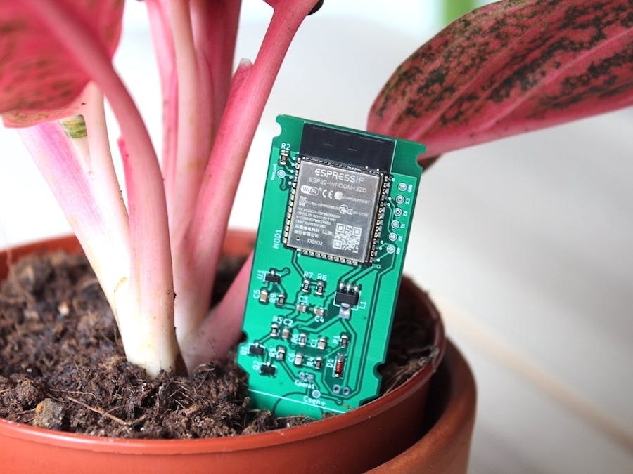
A few months ago, I got my hands on one of these interesting capacitive soil moisture sensors.
These sensors output is an analog value that is proportional to how moist the soil around is. This voltage is based on how the capacitance between two large PCB traces varies, depending on the amount of water in the ground. This great post by wemakethings.net explains their inner working, and I also wrote a little bit about it here.
The First StabTo visualize and store the soil readings, I wanted to try and connect these sensors to MQTT. I put together a little custom board with an ESP32 and a beefy 18650 Li-Ion battery.
This worked okay. The ESP32 sleeps for most of the time and sends an MQTT message via WiFi every few minutes. Here's an example 7-day period of sensor data:
While a few of these boards have been working for a few months, I wasn't super happy with the clunkiness of the PCB, sensor and battery assembly. At this point, I came across Andreas Spiess' video on running an ESP8266 on this tiny LIR2450 coin cell. It seemed like an interesting challenge.
To get rid of all these wires and make a small, all-in-one board, the other challenge was to implement the capacitive sensor itself on a custom board, without relying on the separate sensor module. Again, thanks to the excellent wemakethings.net post, I felt like taking a stab at it.
It took a couple of iterations, but the moisture sensor works. Under the hood, the original sensor module uses a 555 IC to repeatedly charge and discharge the parasitic "capacitor" (the two thick copper traces). Since we have a whole microcontroller there, I use a PWM signal to the same end.
All the design files and PlatformIO code is on GitHub.
On Battery LifeBesides implementing the moisture sensor itself, getting by with a little LIR2450 battery cell has been the most interesting challenge. These coin cells have only around 120mAh in them, and can only source peaks of 200mA. For reference, the ESP32 datasheet mentions peaks of 500mA.
In deep sleep, the ESP32 and the on board voltage regulator (HT7333 LDO) consume around 15uA. This is on the high side of sleeping battery devices, but still manageable. When active, the current is orders of magnitude higher, averaging around 150mA. The name of the game is trying to be as quick as possible and going right back to sleep. Currently, the active time is around 500ms.
WiFi is also relatively power hungry for IoT devices, and simply establishing a connection to access point takes around 300ms on a good day. An interesting alternative is using Bluetooth low energy (BLE) for broadcasting sensor data. On the other hand, we need an additional moving part for piping these BLE packets to MQTT. This is something I want to explore moving forward.
I put together this spreadsheet for estimating the battery life given the active/sleep cycle and battery capacity. Here are some example scenarios:
- LIR2450 cell (120mAh), transmitting every 30 minutes: around 80-90 days.
- 1200mAh LiPo, transmitting every 10 minutes: over a year;
- 18650 Li-Ion (e.g.: 2700mAh), transmitting every 5 minutes: over a year;
I want to experiment with lower power chips such as Nordic's nrf52840. These are BLE-only SoCs and are incredibly energy efficient. They consume only a few microamps during sleep and only around 6mA when transmitting.
A nice goal is to be able to power the whole board with common CR2032 button cells for many months, which I think is doable with these chips. Additionally, we can drop the LDO regulator, since these chips can be powered directly by the whole range of the CR2032 voltage, which also increases the battery life. I will document the progress on my Twitter.
--
Thanks for reading!


Comments
Please log in or sign up to comment.