How to drive a large e-paper display?
E-paper displays require an external frame-buffer, hence the need for a large SRAM.
For example, the 960x672 9, 7" black-white-red e-paper panel requires 161280 bytes and the 960x768 12.2" black-white-red e-paper panel 184320 bytes to store the image to be displayed.
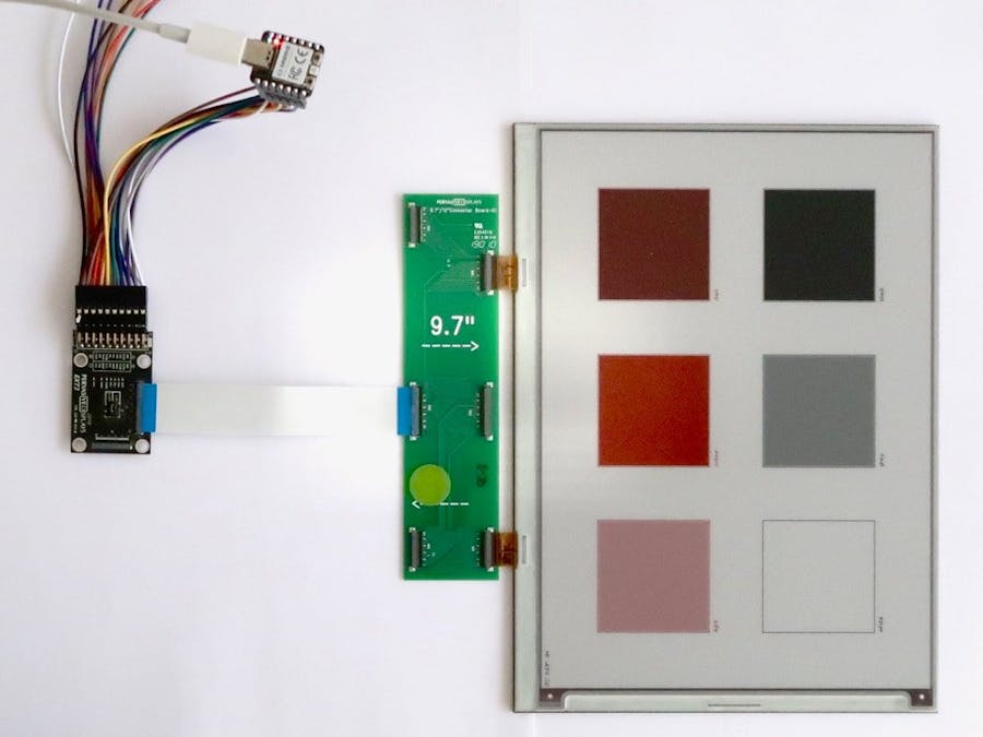
The projet includes the Seeed Xiao RP2040 board, the Pervasive Displays EXT3 extension kit, the EXT3-Giant expansion board, and the 9.7" black-white-red e-paper display.
HardwareThe large e-paper panels are driven by two controllers, hence the need for the EXT3-Giant expansion board and two chip select signals.
Connections between the Xiao RP2040 and the EXT3 extension board include:
- Power with +3.3V and ground;
- SPI signals with clock and MOSI, plus two chip select lines, one for each part of the e-paper panel; MISO and Flash chip select are not used;
- Usual controls with Busy, Data/Command and Reset.
The PDLS_EXT3_Basic library provides all the tools to drive the e-paper panel.
It relies on the Arduino SDK. Installation goes through the standard procedure.
Call the menu Sketch > Include library > Manage library,
- Search for PDLS and
- Select PDLS_EXT3_Basic.
However, the library doesn't include the Xiao RP2040 board by default.
Defining it is easy: just create a pins_t structure and mention the GPIOs for the signals needed.
const pins_t boardXiaoRP2040
{
    .panelBusy = 26, ///< EXT3 and EXT3-1 pin 3 Red -> D0 GPIO26
    .panelDC = 27, ///< EXT3 and EXT3-1 pin 4 Orange -> D1 GPIO27
    .panelReset = 28, ///< EXT3 and EXT3-1 pin 5 Yellow -> D2 GPIO28
    .flashCS = 6, ///< EXT3 and EXT3-1 pin 8 Violet -> D4 GPIO6
    .panelCS = 29, ///< EXT3 and EXT3-1 pin 9 Grey -> D3 GPIO29
    .panelCSS = 7, ///< EXT3 and EXT3-1 pin 12 Grey2 -> D5 GPIO7
    .flashCSS = NOT_CONNECTED, ///< EXT3 pin 20 or EXT3-1 pin 11 Black2 -> N/A
    .touchInt = NOT_CONNECTED, ///< EXT3-Touch pin 3 Orange -> D6 GPIO0
    .touchReset = NOT_CONNECTED, ///< EXT3-Touch pin 4 Red -> D7 GPIO1
    .cardCS = NOT_CONNECTED, ///< Separate SD-card board
    .cardDetect = NOT_CONNECTED, ///< Separate SD-card board
};
NOT_CONNECTED mentions the signal is not implemented.
Using the GPIO numbers instead of the pins names proved to be easier.
The example used for the project is Common_Colours.
#include "PDLS_EXT3_Basic.h"
Screen_EPD_EXT3 myScreen(eScreen_EPD_EXT3_969_0B, boardXiaoRP2040);
Open the Common_Colours.ino file, add the boardXiaoRP2040 board definition and edit the Screen_EPD_EXT3 constructor accordingly.
ConclusionThe compact Xiao RP2040 provides an elegant solution with its fast MCU and large SRAM to drive large e-paper displays, with almost all the pins used.


Comments
Please log in or sign up to comment.