

Hardware components | ||||||
 |
| × | 1 | |||
 |
| × | 1 | |||
 |
| × | 7 | |||
 |
| × | 7 | |||
 |
| × | 1 | |||
Software apps and online services | ||||||
 |
| |||||
 |
| |||||
 |
| |||||
Hand tools and fabrication machines | ||||||
 |
| |||||
 |
| |||||
 |
| |||||
| ||||||
The Configurable Logic Block (CLB) is a hardware peripheral that acts like a small 32 Look-Up Table (LUT) Field Programmable Gate Array (FPGA) inside of a microcontroller. Unlike the full-sized System-on-Chip (SoC) FPGAs on the market (with thousands of LUTs), microcontrollers with the CLB are much lower cost and easier to use. In this demonstration of the CLB, the developer does not need to write any software for the microcontroller – any needed software for the microcontroller is automatically generated by the MPLAB® Code Configurator (MCC).
The CLB inside the PIC16F13145 family of microcontrollers is used to implement a simple electronic die. A 3D-printed custom enclosure mounts the LEDs into the pip (dot) pattern on the die face. There are three pieces of 3D printed material – the cube body, the top plate and an (optional) diffuser mount. LEDs are inserted into the top plate, glued and wired into place. Each pip on the face is wired to a protoboard that slots into the cube base and connects the LEDs to the PIC16F13145 Curiosity Nano Evaluation Kit (EV06M52A), removing the need for an external programmer.
What is the CLB?The CLB is a logic peripheral introduced in the PIC16F13145 family of microcontrollers. It is a small block of programmable logic with 32 Look-Up Tables (LUTs), a 3-bit hardware counter and eight I/O outputs, which support tri-state logic. To configure the CLB, a tool called CLB Synthesizer is used.
CLB Synthesizer is integrated into MCC, but also has a stand-alone web version. This example will use the MCC version, as other peripherals need to be set up, but the web version will generate an equivalent bitstream for just the CLB.
Developing with Zero SoftwareMCC is a (free) GUI based tool for configurating the hardware peripherals in PIC® and AVR® microcontrollers. When the developer is done configuring the peripherals, MCC generates initialization code and an API to call. In the case of the CLB, the CLB Synthesizer generates the bitstream to configure the hardware, then MCC’s initialization code configures the hardware to load the bitstream. Thus, there is no need to add any code to any of the source files in this project.
CLB Synthesizer is also a GUI based tool for configuring the CLB. Hardware gates and elements can be dragged and dropped onto the schematic. Within CLB Synthesizer, one of the files needed is written in Verilog, a Hardware Description Language (HDL), which is used as part of the bitstream and not executed by the CPU.
Theory of OperationThis example uses a simple 3-bit counter that runs fast enough that humans see it as “random”, despite not actually being random. Out-of-the-box, the CLB logic runs from a clock of 50 Hz (20 ms) which drives the debouncing one-shot circuit, counter, and output latches. Using a faster clock will make it harder to predict the output, but this has two drawbacks. Firstly, the faster clock frequencies will make it difficult to see the “rolling” animation as the timer counts. Secondly, the pips will blink faster, which may become a hazard for photosensitive people. The GIF below shows the response at a lower frequency (12.5 Hz, 80 ms).
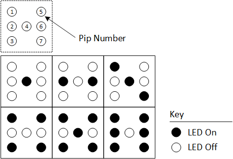
The 3-bit counter runs constantly in the background, even when frozen, with a LUT being used to map the counter value to the appropriate output value for each pip. The diagram below shows the state of the LED for each output.
To freeze the display when stopped, the outputs are only latched when an enable signal is present. The input from the switch is debounced, then fed into a one-shot that inverts a JK flip-flop that controls the enable signal. The RUN/STOP signal is displayed on LED0 on the Curiosity Nano.
Note: If no changes are needed, the only required file is the.hex. This can be downloaded from Github under releases. Unzip the files, then drag-and-drop the hex onto the Curiosity Nano in File Explorer. The remainder of this section will discuss how to program from the development environment.
1. Download a copy of the source code from Github
2. Unzip the files
3. Open MPLAB® X IDE
4. Go-to File → Open Project…
5. Select the Project Folder, in this case: pic16f13145-clb-dice-mcc.X
6. Press the Make and Program Button. This is located on the top toolbar and the icon is an arrow going into a microcontroller.
AssemblyThere are three, 3D printed pieces used for the cube: Body, Top, and a Diffuser mount (Optional). The body of the cube contains a mount for the electronics, while the top of the cube holds the LEDs in place. The body of cube is built for a protoboard of the size 81.3mm x 50.8mm (we used a DKS-SOLDERBREAD-02).
Top of the CubeTo assemble the top of the cube, first insert the LEDs into the mounting holes. Carefully bend the cathode of each LED and solder them together. The cathode is the short-leg on a through-hole LED – however, testing the polarity each LED with a multimeter is highly recommended before soldering. Cut (and reuse) the LED leads as needed.
Carefully solder a wire to this grid. This is the common ground used for the display. (Alternatively, solder a wire to each cathode and bridge them together at one point). Hot glue the grid in place, while trying to keep the LEDs flush and mounted straight. Try to avoid applying hot glue to the anode of the LEDs, as this could remelt/burn in the next step.
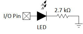
Solder the current limiting resistor to the anode lead of each LED. Hot glue the LEDs in place until they are securely mounted to the top plate.
Cut thin wire (22 AWG recommended) to an appropriate length for each of the seven pips. Strip about 3/8 inches of wire on both sides. Splice the resistor lead onto the wire. This connection should mechanically strong before soldering – a good technique to use is the Lineman Splice. Solder the wires together.
Cut heatshrink tubing to a length that covers all of the exposed metal of the LEDs and resistors. Slide the tubing over the resistor and LED leads, then heat the tubing to shrink it. (A heat gun is recommended, but soldering irons can be used if done carefully). Apply hot glue to support the wiring connections as needed.
Body of the CubeTo assemble the protoboard – the Curiosity Nano can be soldered in place, or a female header socket can be used to hold it in place. (If using the female header, beware of the orientation of the Nano) Solder the leads to the following I/O pins:
- RC6 – Pip 1
- RC7 – Pip 2
- RB7 – Pip 3
- RB5 – Pip 4
- RA2 – Pip 5
- RA1 – Pip 6
- RC0 – Pip 7
- GND – GND
Before continuing, run the program to make sure the display is operating correctly.
Slot the protoboard into the integrated mount. Hot glue the PCB to the cube body to secure it in place.
(Wearing disposable gloves for this step is recommended). Using a gel-type instant-bond glue, apply glue around the edge of the body, then press and hold the top plate in place. After waiting for the glue to bond, release the holding pressure and allow the glue to fully cure. Clean-up any excess.
DiffuserIf using the diffuser (optional), take the 3D printed plate and glue a sheet of paper on top to make a diffuser. The diffuser in the picture is made from parchment paper and glued in place with a glue stick, but the paper easily peels away. We recommend trying another adhesive or switching the parchment paper with normal printer paper. After the assembly is cured, the diffuser plate is attached by pushing onto the LEDs.
Operating the DiceOn Power-on-Reset (PoR), the dice will begin to roll automatically. This is due to the parasitic capacitance on button (SW0) being uncharged, so the button will appear to go from the pressed (0) to the not pressed (1) state after power on.
During normal operation, press and hold SW0 to start and stop the dice. Start and stop are separate button presses – the button is not held to roll the dice.
Modifying the ExampleFrom a development environment (see Programming for setup), press the MCC button in the top toolbar. On first startup, MCC will ask to download the required library files. After loading the files, the screen should look like this.
To adjust the rolling speed, open the TMR2 driver. Under Project Resources (top left side), go to Drivers → Timer → TMR2. In the window that pops-up, modify the Timer Period to set the period. If the desired value is out of range of the current settings, change the clock source or the prescaler values in the section above. After changing the Timer parameters, regenerate the code by pressing the Generate button in Project Resources.
To view / modify the CLB configuration, go to Project Resources → Drivers → CLB.
Note: There is a known issue where the I/O assignments disappear when the CLB driver is opened in MCC. This will be fixed in a future version. To resolve this issue, resynthesize the code.
Since the CLB logic can become complex, it is often beneficial to maximize or float the CLB screen. To maximize the window, double-click on the tab in the toolbar. To return the screen to normal proportions, double-click on the tab again. To float the window, right-click on the tab and select “float”. The CLB window will be detached from the IDE. The window can be reattached by dragging the tab back into the tab bar. Note: the window positions and sizes in the IDE can be reset under Window → Reset Windows.
After modifying the CLB logic, press the synthesize button in the bottom left of the screen. If it passes, a checkmark will appear along with a bar indicating the LUT utilization of the design. Once the design has been synthesized, the MCC code must be regenerated. On the left side, press the “Generate” button next to Project Resources to remake the MCC files.
If the synthesis fails, an X will replace the checkmark. Error messages from the CLB synthesizer can be viewed by pressing the hamburger button next to the words “CLB Synthesizer”, opening preferences and checking the option for “Show Output”.
If this example was remade in software, the CPU will be a lot busier. Unlike the current implementation, where the CPU is fully idle, the software approach would have to periodically generate an interrupt, increment a counter, run counter logic and then map the counter value to the correct I/O states. None of that is difficult for the CPU to perform, but it does require the CPU to switch from another task, which might be more time or latency sensitive.
Another disadvantage is that the dice update rate is very stable with the CLB, while the CPU would need to use interrupts to get close to the same level of stability. If the code was polled (instead of interrupt driven), small delays in execution would cause the refresh rate to vary. By performing tasks like these in hardware peripherals, the load on the CPU is reduced, performance is improved, and power consumption is lowered. For more information about the CLB, please see the peripheral page or read the PIC16F13145 datasheet.


_3u05Tpwasz.png?auto=compress%2Cformat&w=40&h=40&fit=fillmax&bg=fff&dpr=2)
Comments
Please log in or sign up to comment.