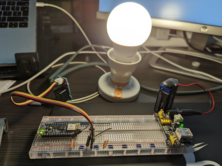
I decided to make an Internet-connected light that I could also control physically.
Please note that this project uses alternating current and you will need to be extremely careful so you don't get electrocuted. Even touching the relay while it is powered could send a jolt through you. Please be careful.
I kept this simple by using the Arduino Nano RP2040 Connect. This microcontroller has an integrated WiFi radio so I can connect it to the internet.
Step 1: PlanningI wanted a lamp that I could control both physically and remotely. In order to satisfy that requirement, the physical switch would need to be a toggle: one press to turn it on and another to turn it off. That way the lamp could be turned on or off either physically or remotely.
In order to control alternating current (AC) from a microcontroller, I had to introduce a relay. When you pick a relay you need to check the rating for the type of current and voltage that you need to support. The relay I went with supports a peak voltage of 250V at 10A. This worked for me because I was only powering a light bulb.
I chose the Arduino Nano RP2040 Connect because it has a WiFi radio and is supported by the Arduino IoT Cloud. If it wasn't supported I would need to write extra code for the cloud layer, and I wanted to avoid that at this stage.
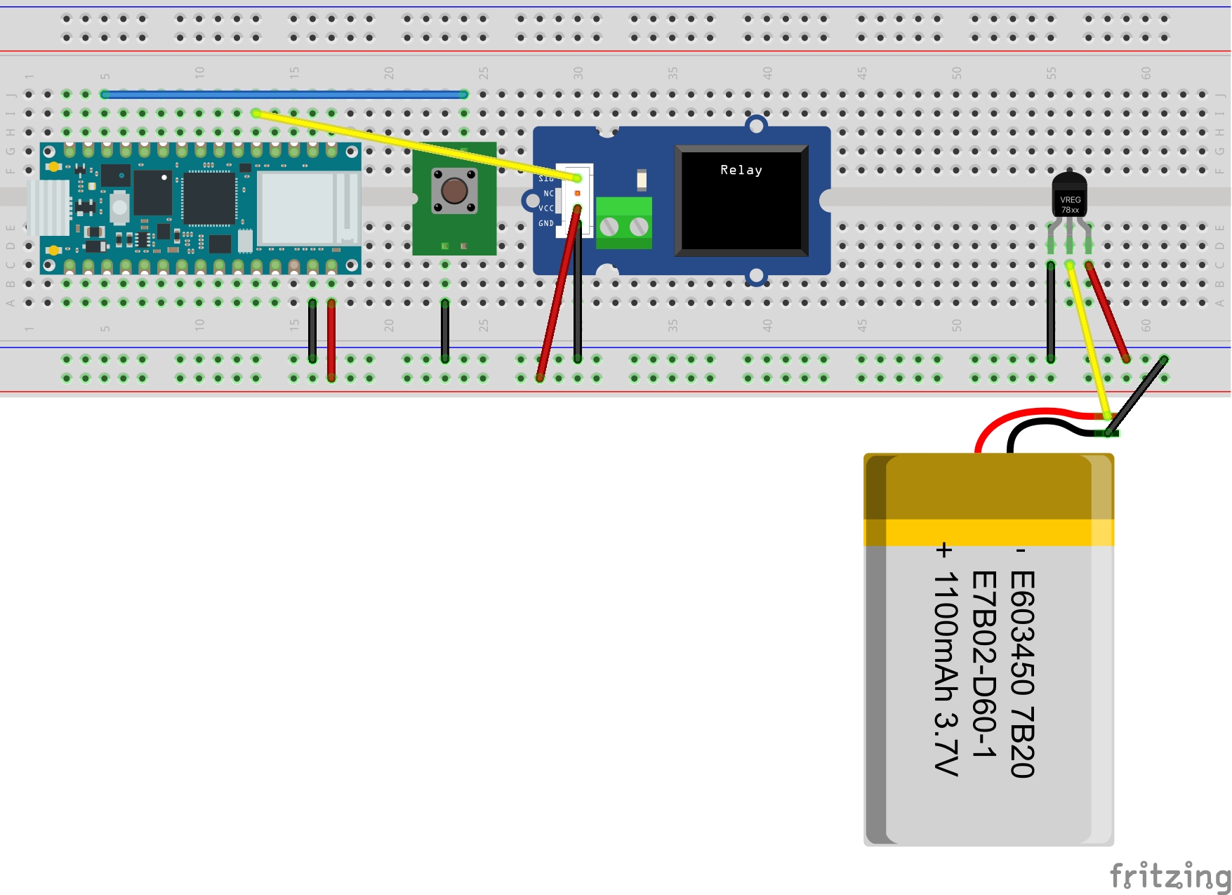
Grove components normally utilize a Grove shield. I got a male-pin to Grove converter so I can use the relay with a breadboard.
Step 2: The LampMy advice for getting started is to build the AC component first. Take your mains cord and snip off the end that doesn't connect to the wall. Next, strip off some of the insulation on the wires and attach these to the lamp holder. Be careful so that you don't leave any exposed wires. Finally, screw in your lamp and plug it in. The lamp should turn on. If it doesn't, please debug it at this point. You will need to remove it from the wall to turn it off.
Step 3: The DC ComponentsI introduced a battery into the mix so I can operate the system without using USB power. To use a battery you will need to regulate the voltage to 5V or 3.3V otherwise you will destroy the microcontroller. This part is completely optional.
One leg of the button is connected to D10, with the other leg connected to GND. This is connected as a digital input with a pull-up resistor.
The relay is connected to VCC and GND as indicated by the colors of the cables. The yellow cable is connected to D2. This is treated as a digital output.
Step 4: Offline CodeI always write my code to work offline before I introduce any networking components. This helps with any debugging. Tactile buttons can be difficult to work with when you want to toggle the state of a variable. This can be difficult to debug. The approach I took was to introduce debouncing. The code is shown below.
#include <Bounce2.h>

const int pin = 2;
const int button = 10;
bool led_state = false;

Bounce bouncer = Bounce();

// the setup function runs once when you press reset or power the board
void setup() {
    pinMode(pin, OUTPUT);
    pinMode(button, INPUT_PULLUP);
    bouncer.attach(button);
}

// the loop function runs over and over again forever
void loop() {
    bouncer.update();
    if (bouncer.changed() && bouncer.read() == LOW) {
        led_state = !led_state;
        Serial.println(led_state);
    }
    digitalWrite(pin, led_state);
}
If everything works as it should the relay will turn on and off when you push the tactile button.
Step 5: Cloud SetupIf you don't have an account on the Arduino IoT Cloud, please go ahead and create one.
Next, go to the Devices tab and register your microcontroller. This could take up to five minutes so please be patient.
This step is actually three different activities. Think of a Thing as the complete unit that contains your microcontroller, in this case, your IoT device. Our Thing is a lamp, so you can call it that.
You will need to configure three different components:
- Variables: these are the things that change. In this case, it's whether our light is on or off. I called the variable lights and gave it a boolean type. I also made it read & write so both the device and the cloud environment can change the value.
- Associate a device. This step lets the platform know what microcontroller to read and write these variables.
- Network: This configures the device so that it has access to the internet.
With the above configuration complete, click on the Sketch tab.
Unlike the Arduino IDE, the sketch will not be empty. The setup() and loop() functions will have some code in them. Be sure to leave them in there.
You can scroll to the bottom of the sketch to see an event handler for when the lights variable changes on the cloud. This is useful for doing something but I don't use it here because I handle change in the loop() function.
You will need to update the sketch so that it recognizes the pin and relay and does the right thing when the button is pressed. This is shown in the code snippet below.
You can verify the code and deploy it to the device from this interface. There is also a more full-fledged editor that shows you other files that you can't see at the moment. For example, not that this sketch doesn't show you how the WiFi connection is established or what the credentials are.
Go ahead and test that this works as expected.
Step 8: Connect the lamp to the relay- Disconnect both the lamp and the Arduino boards from power.
- Splice any part of the cable on the lamp.
- Cut the neutral wire and strip two ends.
- Connect both ends to the relay.
- Connect the Arduino and check that it works and the relays lights up as you toggle.
- Connect the lamp to power and try the whole system.
Dashboards give you a way to monitor and control your variables. Arduino IoT Cloud also has a mobile application that gives you access to your dashboards. Follow the steps below to set up a dashboard.
- Navigate to the Dashboard Tab and Click on the Create button.
- Give your new dashboard a name.
- Click on the Add button and choose an appropriate widget for your variable. In this case, I chose a toggle.
- Link the widget to a variable. You can add as many widgets as you would like to a dashboard.
Once you set your dashboard to viewing mode (the eye besides the pencil, you can use the widget to control your lights!
Congratulations.


Comments
Please log in or sign up to comment.