For a Perfect Home Automation, I selected these points
- Compact
- IoT Enabled
- Works without internet
- Features
- Easy to Install
- Long Life
For making a system like this I break this operation into 3 parts
- Hardware Phase
- Software Phase
- Installation Phase
For designing a perfect PCB for the perfect home automation system we need a perfect PCB designer. For this, I am using Altium Designer which is also the sponsor of this video. Let me show you an overview of my design.
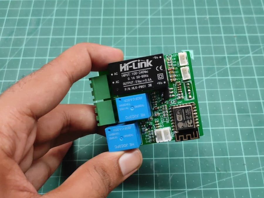
While designing this board I kept in mind to keep the board as compact as possible without compromising on any feature. Let’s look at the components on the board.
We have an esp8266 chip, then We have two relays, and a compact power supply. I also added screw connectors for AC, JST connectors for touch switches and sensors. 0603 SMD resistors and capacitors were used to reduce the size of the PCB.
I could be more compact If I used 0402 resistors and capacitors, but we can’t solder such tiny components at home. Altium worked amazing in this design. You can get one month free for Altium designer software if you download it from here.
So, the design is complete now we have to order these PCBs. Let’s go to jlcpcb.com and upload our Gerber files in the quote section.
Then select color, quantity, and thickness and add them to the cart. Finally, go to the cart and check out our order.
In just 5 days I got the PCB’s and they look amazing as expected. JLCPCB service is fast and cheap. Overall PCB looks great and now it's time to collect components for this PCB and start soldering.
I started with small components such as resistors capacitors and diodes.
To solder them we need a sharp tip soldering iron. a sharp tweezer and thin solder. For cleaning, you can use alcohol.
To solder put some solder in one of the pads then take a tweezer and pick up the component and place it right in its place. Keep it holding and put soldering iron and melt the solder and remove it.
One of the sides will get soldered. Now you can solder another side easily.
By using the same method I soldered all components. The final PCB looks something like this.
Isn't it amazing???
Now I took a touch button and soldered it with a connector. Now we can directly plug it in the connector. In the way, I soldered a temperature and humidity sensor.
You watch this video for a detailed process.
So, the hardware section is complete.
Firmware SectionArduino IDE Installation
1. Visit http://www.arduino.cc/en/main/software to download the latest Arduino IDE version for your computer’s operating system. There are versions for Windows, Mac, and Linux systems. At the download page, click on the “Windows Installer” option for the easiest installation.
2. Save the.exe file to your hard drive.
3. Open the.exe file.
4. Click the button to agree to the licensing agreement:
5. Decide which components to install, then click “Next”:
6. Select which folder to install the program to, then click “Install”:
7. Wait for the program to finish installing, then click “Close”:
8. Now find the Arduino shortcut on your Desktop and click on it. The IDE will open up and you’ll see the code editor:
ESP8266 Boards Installation
To install the ESP8266 board in your Arduino IDE, follow these next instructions
- In your Arduino IDE, go to File> Preferences
- Enter http://arduino.esp8266.com/stable/package_esp8266com_index.json into the “Additional Boards Manager URLs” field as shown in the figure below. Then, click the “OK” button:
Note: if you already have the ESP32 boards URL, you can separate the URLs with a comma as follows:
https://dl.espressif.com/dl/package_esp32_index.json, http://arduino.esp8266.com/stable/package_esp8266com_index.json- Open the Boards Manager. Go to Tools > Board > Boards Manager…Search for ESP8266 and press the install button for the “ESP8266 by ESP8266 Community“:
- That’s it. It should be installed after a few seconds.
To install a new library into your Arduino IDE you can use the Library Manager (available from IDE version 1.6.2). Open the IDE and click on the "Sketch" menu and then Include Library > Manage Libraries.
Then the Library Manager will open and you will find a list of libraries that are already installed or ready for installation. Search for Blynk library and in the version, selection choose the latest version to date
Finally, click on Install and wait for the IDE to install the new library. Downloading may take time depending on your connection speed. Once it has been finished and Installed tag should appear next to the Bridge library. You can close the library manager.
You can now find the new library available in the Sketch > Include Library menu.
Now you need a USB to UART converter and solder VCC Ground RX and TX wires from the converter to the board.
Download this code from the article and open It in Arduino IDE.
Now add your wifi credentials here and your Blynk auth token here. You will get Blynk auth token from the blynk mobile app. Everything in detail is available in the article. So don’t worry.
Finally, it's time to upload the code.
While uploading the code you first need to set esp to flash mode.
To do this take a tweezer and put it between the flash holes in the PCB. Then using another tweezer touch the reset pads. The esp will be set to flash mode.
Now upload the code.
Now we are ready to rock.
I installed this PCB on an extension board. Touch switches are pasted using a glue gun on the backside of the blanks. And the humidity sensor is glued to the case.
Finally, it is completed
The Blynk app is available for both iOS and Android devices. Click one of the buttons below to get started downloading the app:
BLYNK FOR IOSBLYNK FOR ANDROID
After downloading the app, create an account and log in. Welcome to Blynk!
Next, click the "Create New Project" in the app to create a new Blynk app. Give it any name you please, just make sure the "Hardware Model" is set to ESP8266.
The Auth Token is very important -- you'll need to stick it into your ESP8266's firmware. For now, copy it down or use the "E-mail" button to send it to yourself.
Add Widgets to the ProjectThen you'll be presented with a blank new project. To open the widget box, click on the project window to open.
Add a Button, then click on it to change its settings. Buttons can toggle outputs on the ESP8266. Set the button's output to VirtualV2.
Add one more button to VIrtual V3.
Now add two Labeled Value to Virtual V1 and Virtual V0
In label for V1 use Temp - /pin/C
for V0 use Humidity - /pin/%
Project is completed here


_ztBMuBhMHo.jpg?auto=compress%2Cformat&w=48&h=48&fit=fill&bg=ffffff)


Comments
Please log in or sign up to comment.