The concept of working of line follower is related to light. We use here the behavior of light at ablack and white surfaces. When light falls on a white surface it is almost fully reflected and in the case of ablack surface light is completely absorbed. This behavior of light is used in building a line follower robot.
In this Pi Pico-based line follower robot, we have used IR Transmitters and IR receivers also called photodiodes. They are used for sending and receiving light. IR transmits infrared lights. When infrared rays fall on a white surface, it’s reflected back and caught by photodiodes which generate some voltage changes. When IR light falls on a black surface, light is absorbed by the black surface and no rays are reflected back, thus photodiode does not receive any light or rays.
Here in this Pi Pico line follower robot when the sensor senses white surface then Pi Pico gets 1 as input and when senses black line Pi Pico gets 0 as input.
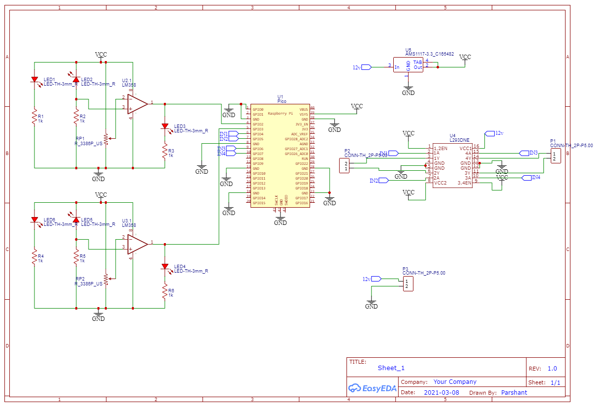
Circuit ExplanationThe whole PiPico line follower robot can be divided into 3 sections: sensor section, control section, and driver section.
Sensor section:
This section contains IR diodes, potentiometer, Comparator (Op-Amp), and LEDs. The potentiometer is used for setting reference voltage at the comparator's one terminal and IR sensors are used to sense the line and provide a change in voltage at the comparator’s second terminal. Then comparator compares both voltages and generates a digital signal at output. Here in this line follower circuit, we have used two comparators for two sensors. LM 358 is used as a comparator. LM358 has inbuilt two low noise Op-amps.
Working of Line Follower Robot using Pi PicoWorking of line follower is very interesting. Line follower robot senses black line by using sensor and then sends the signal to Pico. Then pico drives the motor according to sensors' output.
Here in this project, we are using two IR sensor modules namely the left sensor and the right sensor. When both the left and right sensor senses white then the robot moves forward.
If the left sensor comes on a black line then the robot turn left side.
If the right sensor sense a black line then the robot turns right side until both sensors come at a white surface. When the white surface comes robot starts moving on forward again.
If both sensors come on the black line, the robot stops.
This is a circuit for LFR.
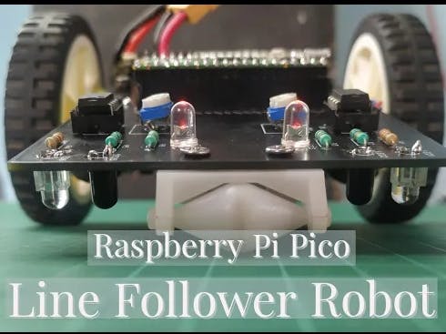
We design a line follower robot using the new microcontroller Raspberry Pi Pico Board.
There were 3 sections of the PCB
1. the First one was the IR sensor section
2. the Second one was the motor driver section
3. The last section was the pico section
The IR sensor section was designed by using lm358 operational amplifiers, pairs of IR emitter and IR receiver, a potentiometer, and some resistance.
IR sensors of this kind can be used to determine the difference between white and black.
the IR emitter throws light on the surface and the IR receiver receives it.
In the case of black color, the IR rays emitted by the emitter are absorbed. So output remains zero
In the case of white color, the IR rays are reflected and received by the receiver. So we get high output.
Coming to the motor driver section
The Motor Driver Section includes L293D motor driver ic and connectors for the motors and battery. L293D is based on H-Bridge. If you want to get more information about motor drivers. I have given a link in the description you can check out that.
The raspberry pi section includes raspberry pi and a 3.3v voltage regulator. Pi works on 3.3v so we used a voltage regulator AMS1117.
Order PCBsLet's order the PCB from JLCPCB.com. go to fabrication and get PCB fabrication files and click order at JLCPCB. JLCPCB order page will open.
Verify dimensions and select no of PCBs. Select surface finish and click add to cart. Now let's check out, fill in your details, and pay using PayPal.
$2 for 1-4 Layer PCBs, sign up to get $18 new user coupons: https://jlcpcb.com/IYB
Fun fact With over 10 years of experience in PCB manufacturing, JLCPCB has more than 200, 000 customers, with over 8, 000 online orders of PCB prototyping and small quantity PCB production per day.
after a week I got the PCBs. Matte Black color looks awesome.
CodingLet’s open VS Code.
To program pico you will need a PICO-go extension installed in your vs code. For more information watch my pico tutorial series click here
It worked fine.
The LFR follows the black line. I programmed it to stop working when both sensors touch black. So on this side of the paper, it stops at every intersection.


_ztBMuBhMHo.jpg?auto=compress%2Cformat&w=48&h=48&fit=fill&bg=ffffff)


Comments
Please log in or sign up to comment.