


Hardware components | ||||||
| × | 1 | ||||
Hand tools and fabrication machines | ||||||
 |
| |||||
Live Voltage Detector
There are some occasions that we need to troubleshoot mains electrical connections. Most of the electricians now use non-contact voltage detectors. Using these types of tools, we can detect whether the wire has a live voltage or not. Because of this tool, there is no need to remove the covers of the sockets or connectors. Some of the testers can detect live voltage even behind a wall. But these tools cost a lost and making such investment to use a couple of times per year is not economical. Well, how about if you can build your own non-contact live voltage detector? These non-contact live voltage detectors use the electromagnetic field emitting from the voltage in the wires and amplify it to indicate the presence of the voltage. To build this device we are going to use C1815 transistors and a few other components. You can see the pinout and the appearance of the C1815 transistor in the below image.
Key Parts :
There are few more electronic spare parts that we will need to assemble this circuit other than the C1815 transistors.
5. Circuit wire & Copper Wire
6. LED
Required Tools :
1. Soldering Iron
2. Iron Stand
3. Flux
4. Nose pliers
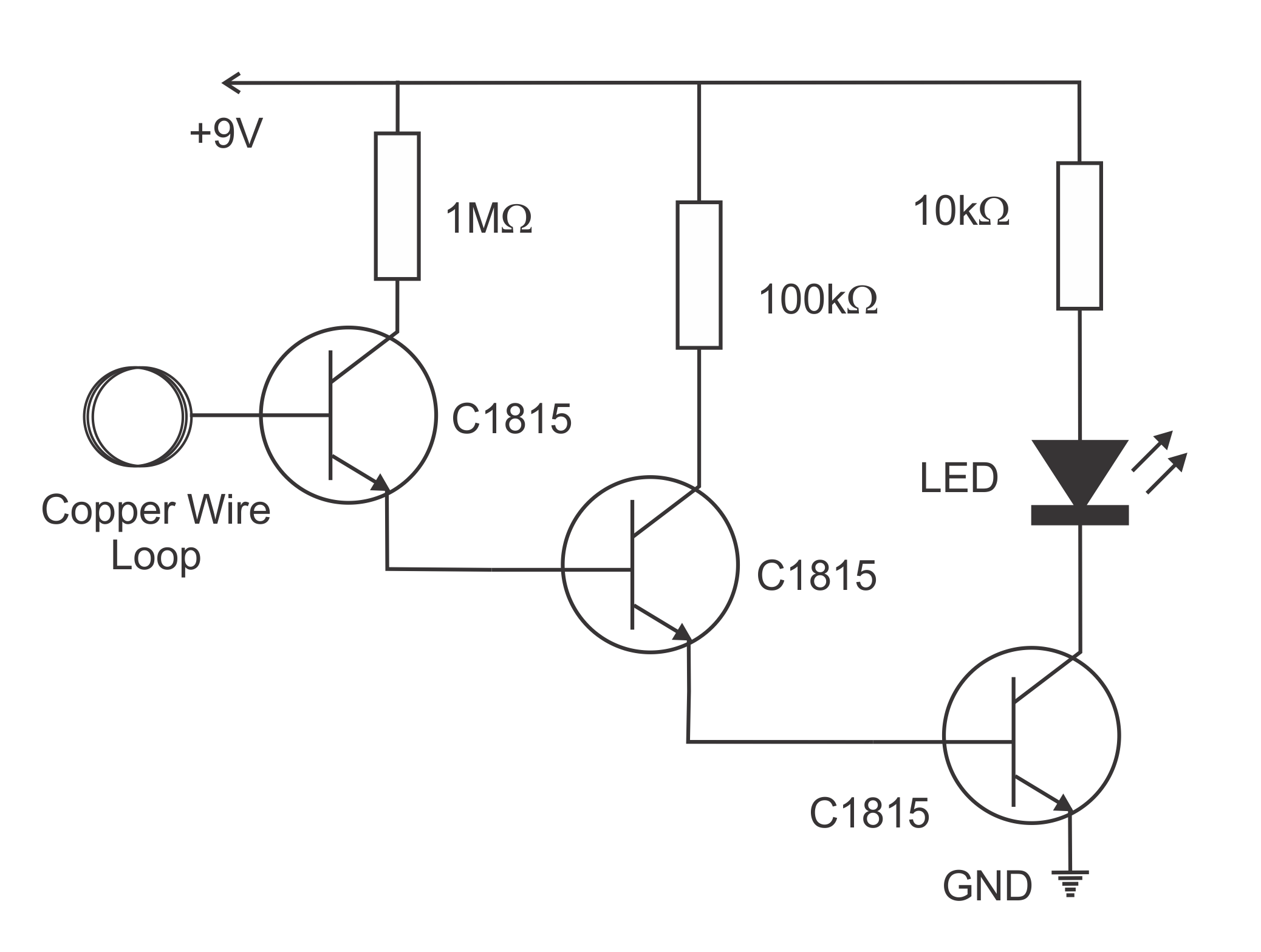
Circuit Diagram:
This is the basic circuit diagram of the live voltage tester. There are three C1815 transistors in the base to emitter configuration. A copper loop is connected to the base pin of the first transistor and emitter of the first transistor is connected to the base of the second transistor. A LED with a current limiting resistor is connected to the collector of the third transistor. This circuit can be powered from a 9V battery
Step By Step Guide:
Step 1: Arrange the components
Step 2: Solder the transistors as shown in the circuit diagram.
Step 3: Solder 1MΩ resistor to the collector of the first transistor.
Step 4: Solder 100kΩ resistor to the collector of the second transistor.
Step 5: Solder the negative pin of the LED to the collector of the third transistor
Step 6: Solder 10kΩ resistor to the positive pin of the LED
Step 7: Solder the battery connection and the copper wire loop.
Step 8: The circuit is now ready you can test it.
How It Works:
The three transistors are in a configuration that signals from the first transistor amplify by the second transistor and the output signal of the second transistor is amplified by the third transistor. When a weak signal is picked up by the first transistor from the copper wire loop, this signal will further be amplified by the second and third transistors and then it will trigger the LED.
Conclusion:
This circuit is very useful for day to day electrical troubleshooting. And there is no risk of getting electrocuted. If you need other IC chips, IGBT, Transistor and so on, please visit UTSOURCE

Comments
Please log in or sign up to comment.