


Hardware components | ||||||
_ztBMuBhMHo.jpg?auto=compress%2Cformat&w=48&h=48&fit=fill&bg=ffffff) |
| × | 1 | |||
| × | 1 | ||||
 |
| × | 1 | |||
 |
| × | 1 | |||
 |
| × | 1 | |||
 |
| × | 1 | |||
 |
| × | 1 | |||
 |
| × | 1 | |||
Software apps and online services | ||||||
 |
| |||||
 |
| |||||
In this tutorial we will learn how to detect shock vibrations using a simple Piezoelectric sensor Vibration module and Visuino.
Watch a demonstration video.
Step 1: What You Will Need- Arduino UNO (or any other Arduino)
- Piezoelectric shock Vibration module
- OLED display
- Jumper wires
- Breadboard
- Visuino program: Download Visuino
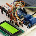
Connect Arduino positive pin [5v] to breadboard red line pin [positive]
Connect Arduino positive pin [GND] to breadboard blue line pin [negative]
Connect Piezo module pin [V] to breadboard positive pin [red line]
Connect Piezo module pin [G] to breadboard negative pin [blue line]
Connect Piezo module pin [DO] to arduino digital pin [7]
Connect OLED pin [VCC] to breadboard positive pin [red line]
Connect OLED pin [GND] to breadboard negative pin [blue line]
Connect OLED pin [SDA] to Arduino pin [SDA]
Connect OLED pin [SCL] to Arduino pin [SCL]
Step 3: Start Visuino, and Select the Arduino UNO Board TypeTo start programming the Arduino, you will need to have the Arduino IDE installed from here: https://www.arduino.cc/.
Please be aware that there are some critical bugs in Arduino IDE 1.6.6. Make sure that you install 1.6.7 or higher, otherwise this tutorial will not work! If you have not done follow the steps in this tutorial to setup the Arduino IDE to program Arduino UNO! The Visuino: https://www.visuino.eu also needs to be installed. Start Visuino as shown in the first picture Click on the "Tools" button on the Arduino component (Picture 1) in Visuino When the dialog appears, select "Arduino UNO" as shown on Picture 2
Step 4: In Visuino Add Components and Connect ThemAdd Components
- Add "text value" componentSelect "TextValue1" component and in the properties window set "Value" to "VIBRATION DETECTED"
- Add "Delay" componentIn properties window set "Interval (uS)" to 2000000
- Add "SSD1306/SH1106 OLED Display (I2C)" componentDouble click on "DisplayOLED1" component and in the elements window drag "Text Field" to the left and drag "Fill Screen" to the leftSelect on the left "Text Field1" and in the properties window set "Size" to 1, "x" to 0, "y" to 50
Connect components
- Connect Arduino digital pin out [7] to "Text Value1" component pin [clock]
- Connect Arduino digital pin out [7] to "Delay" component pin [start]
- Connect "Text Value1" component pin [Out] to "DisplayOLED1" > "Text Field1" pin [In]
- Connect "Delay1" pin [Out] to "DisplayOLED1" > "Fill Screen1" pin [Clock]
- Connect "DisplayOLED1" pin [Out] to Arduino I2C pin [In]
In Visuino, at the bottom click on the "Build" Tab, make sure the correct port is selected, then click on the "Compile/Build and Upload" button.
Step 6: PlayIf you power the Arduino UNO module, and shake the piezo sensor you should see a message written on the OLED display.
Congratulations! You have completed your project with Visuino. Also attached is the Visuino project, that I created for this tutorial, you can download it here.You can download and open it in Visuino: https://www.visuino.eu


Comments
Please log in or sign up to comment.