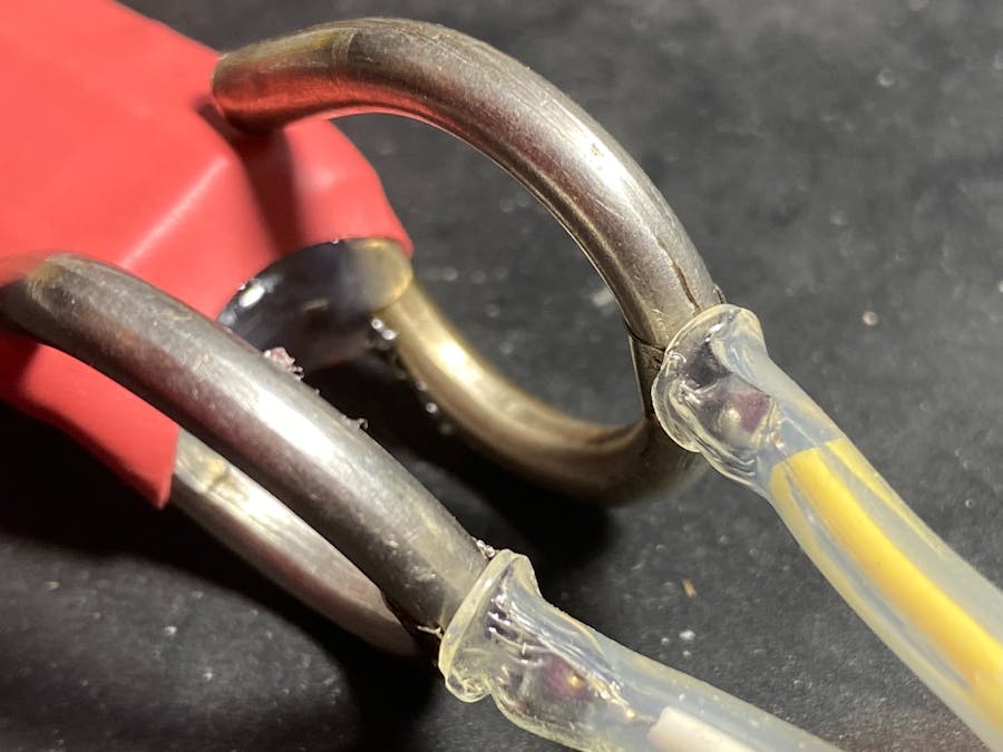
Experimenting with hobbyist garden soil moisture sensors printed on PCB material, I found they corroded away quickly (electrolysis?). I had a look at commercially available more robust solutions but was unsatisfied.
This type of sensor is as simple as an electronic device can possibly be, you can make an immediate equivalent by sticking the two probes from your multimeter into the soil and measuring the resistance. As the soil moisture increases the resistance between the probes decreases. That's it. It's a circuit with one variable resistor which is the soil.
Calibrating a probe unit is straight forward. The material of the probe, its length, the distance between the probe prongs will vary the resistance values achieved. Putting the probe into pure water gives the minimum resistance / maximum moisture value. Dry clean probes (i.e., just the air gap) should be open circuit, the maximum resistance / zero moisture value.
A lot of kits available add a generic LM393 style comparator module to enable analogue and digital outputs. This might be useful for your application, but equally may be unnecessary.
So I was on a search for more robust probes, that would last in the garden indefinitly.
I had some old stainless steel tent pegs hanging around. I initially thought, "how hard can it be to solder or braze on a connection to some hookup wire?" Experimentation showed the answer is that it's pretty hard. I was unsuccessful. I couldn't get enough heat, the right solder, or the right flux, and my attempts were misshapen and not useful.
The project went on to the back burner for a year until recently I bought a spot welding machine for making up battery packs. There's a heap of varieties of these machines and kits out there for every budget. I wondered whether the same technique would be useful for my tent peg probes. If I could spot weld on the same nickel tape that is used in battery packs, I could easily solder hook up wire to those.
Turns out it works a treat.
The current iteration of the probes quickly evolved from there. The steps I followed were:
- Spot welded on a short nickel tape tag to each of the two pegs
- Put heat shrink on the shaft of each peg where the seperator was to go (I was worried about the wood becoming wet and conductive).
- used 8x8mm pine as a seperator, and initially lashed the two pegs and the seperator together with kapton tape.
- Covered the seperator with more heatshrink and sealed each end with hot glue. Used the heat gun to make sure the hot glue got really hot and settled in to all the gaps forming a good plug on each end.
- Soldered on the hookup wire and covered with more heatshrink.
- And finally, tested the new probe with a multimeter and a glass of water. 1.23 M ohms (deep water), 1.37 M ohms (shallow water).
Next iterations will be adding a suitable microcontroller, battery, and solar panel to get the new probe out into the garden.


Comments
Please log in or sign up to comment.