

Hardware components | ||||||
 |
| × | 1 | |||
| × | 1 | ||||
| × | 1 | ||||
| × | 1 | ||||
 |
| × | 1 | |||
 |
| × | 1 | |||
| × | 1 | ||||
| × | 2 | ||||
| × | 2 | ||||
| × | 2 | ||||
| × | 1 | ||||
| × | 1 | ||||
| × | 1 | ||||
| × | 1 | ||||
| × | 1 | ||||
| × | 1 | ||||
Software apps and online services | ||||||
 |
| |||||
| ||||||
| ||||||
Hand tools and fabrication machines | ||||||
| ||||||
This project started with a simple idea--I wanted to be able to monitor the position of my garage door, and send myself a reminder to shut the garage door if it was left open late at night (there have been several times when we accidentally left it open all night....). We have a Genie II garage door opener, which is the original opener when the house was built in 2000.
As I looked into simply monitoring the garage door position, I realized it was possible to do a lot more...
Data Collection (Scoping)Using a voltmeter, I did some initial investigating, and found the following useful information:
- There are two limit switches on the drive track, one switch that is closed when the door is fully shut, and the other switch that is closed when the door is fully open. (These are the switches that are used to control opening & closing the door). A single wire leads back from each switch to the garage door head unit. Each wire reads + 5 VDC to ground when the switch is open, and 0 VDC when the switch is shut. Based on this, the following truth table could be constructed:
Up Switch Down Switch Door Position
======================================
+5 VDC 0 VDC Fully shut
+5 VDC + 5 VDC Intermediate
0 VDC + 5 VDC Fully Open
0 VDC 0 VDC error (should never happen)
- The wall switch has two buttons with only a pair of wires leading to the head unit. One wire (white) is connected to ground (Terminal 2) on the connection block, and the other wire (red) that is + 5 VDC, and connected to Terminal 1.
- When Terminal 1 is shorted to Terminal 2, the garage door opens or shuts, just like pushing the "door" button on the wall switch.
- When Terminal 1 is shorted to ground through a resistor between ~220 and ~450 ohms, the garage light on the opener turns on or off, just like pressing the "light" button on the wall switch.
With this, I had the information I needed to design a Particle Photon-based monitoring system, and also remotely control the door and light.
Since I was going to install a Photon in the garage, I thought it would be useful to monitor the following additional information:
- Temperature / humidity
- Light level (brightness)
- Motion
Passive Infrared (PIR) Motion Detector and Photoresistor
Based on earlier projects, I wanted to move the HC-SR501 PIR and photoresistor away from the Photon and the head unit, so I bought a single gang surface mount junction box and plain cover. The plastic "lens" on the PIR is slightly above 7/8" in diameter, so I drilled a 7/8"hole in the plain cover, and used a file to make it a bit bigger so the PIR would sit flush against the cover, with the lens sticking through. Two very small screws & nuts (0-80 x 3/8") were used to hold the PIR board to the cover. I also drilled two small holes for the photoresistor leads.
I use 24 gauge category 5 (CAT 5) solid wire with DuPont connectors to make the connections (female for the PIR / photoresistor, male for connection to breadboard / controller). This makes for a cleaner, more professional-looking project and better connections.
The PIR has three configurable options. I set sensitivity to the middle of the range, the timeout feature to ~60 seconds, and the retrigger option to allow retriggers (that is, the PIR output will stay HIGH until all motion has stopped for the timeout duration).
Here are a couple of pictures of the PIR / photoresistor single gang box, before & after installation:
DHT-22 Connection
Similar to the PIR / photoresistor, I wanted to locate the DHT22 away from the head unit, and also not near the garage ceiling, to avoid any stagnant air. To do this, I install DuPont connectors on 3 strands of Category 5 cable, and connect to the DHT22. I also use heat shrink tubing for a cleaner, more professional appearance.
ControlEverything 2 Relay Shield
Since I wanted to control two inputs, I selected two relay shield for the Particle. I saved a lot of time because I didn't have to fabricate anything; all I had to do was put in a mini breadboard for resistors and to patch up inputs. The support and library provided by ControlEverything were easy to use. There are also a lot of features (both firmware-supported and hardware) that I am not using in this application. One nice feature is additional general purpose input-output (GPIO) ports.
4 11/16" Work Box Layout
Using machine screws, bolts, and 1/2" PEX water tubing, I installed the ControlEverything 2-relay shield about 3/8" above the back of the in the 4 11/16" work box, with the power connection lined up with one of the punched holes. (I had to drill extra holes in the box to mount the relay shield, and also holes to mount the finished box to the angle iron which holds the garage door head unit).
A mini breadboard was mounted on the side of the work box for connections & components (resistors) to be installed.
Because of the location in the garage and the metal cover that would be installed on the finished project, I connected an external 2.4 GHz antenna to the uFL connection on the Photon.
Black rubber grommets were installed on all holes that had cables / wires passing through them.
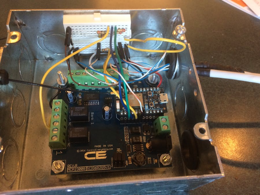
This picture shows the box with the relay shield and mini breadboard installed, with the PIR / photoresistor and DHT22 connected. This was not the final wiring, but an intermediate point when I was still testing the assembly.
Final Installation
The finished enclosure was bolted to the angle iron holding the garage door head unit. The wires leading to the Up and Down limit switches were cut, and pickup wires were spliced in with wirenuts and lead to the applicable locations on the mini breadboard. A single wire was run from the ControlEverything relay 1 NO (normally open) contact to the garage door head unit input terminal 1 (shown above). Finally, the uFL external antenna was run to a 1" x 3" furring strip that I mounted above the head unit, to keep a strong WiFI signal to my home router. The power supply for the ControlEverything relay shield (which also powers the Photon) was plugged into the outlet on the ceiling. You can also see the DHT22 hanging in free air above the enclosure. Here's what it looks like:
Here's a picture of the complete installation from a bit farther back, showing the electrical box with the PIR and photoresistor.
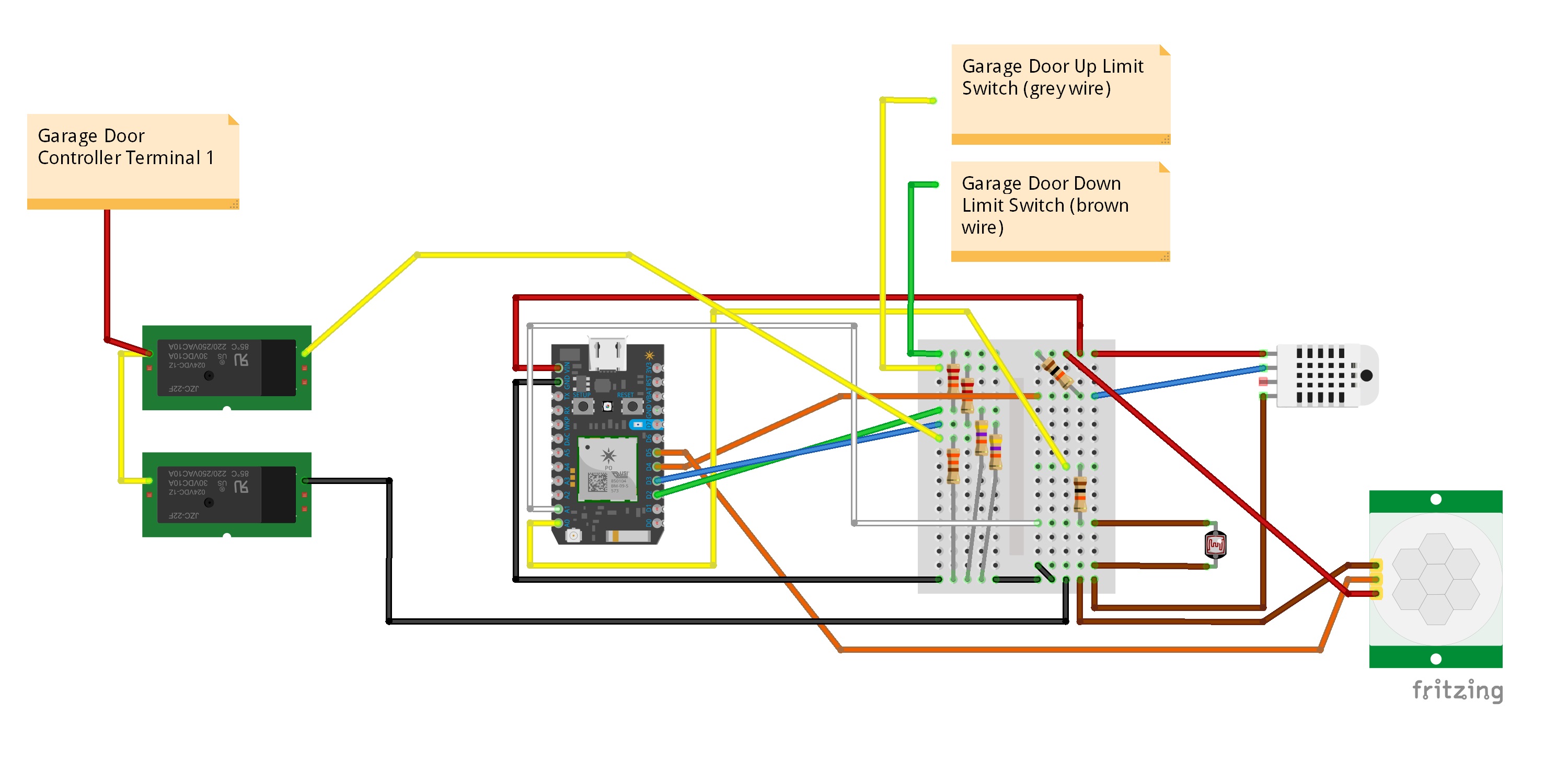
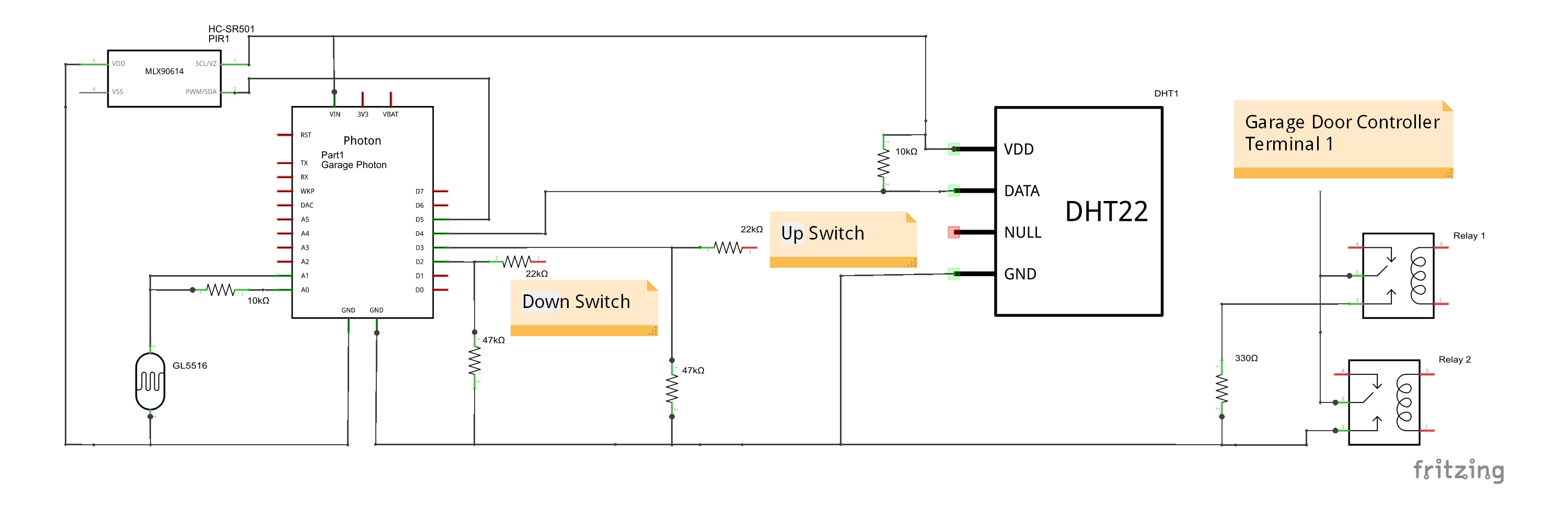
Electrical Design (Circuitry)
Even though the Photon's digital I/O ports can tolerate 5 VDC, I decided to drop the 5 VDC from the door switches to 3.4 VDC using a 22 kohm / 47 kohm voltage splitter. (Somewhere along the way I have burned out digital ports D0 and D1, they don't work any more, which I didn't want to repeat).
Since the resistance range to toggle the garage light was 220 - 450 ohms, I chose the closest mid-point value of 330 ohms.
A 10 kohm pullup resistor was used between Vin and the DHT22 signal line.
A 10 kohm resistor was used with the photoresistor to split the 3.3 V from analog port A0. This value, combined with the resistance of the GL5516 photoresistor in typical light conditions, gives a good range for analog measurement and conversion.
Design - Firmware
The firmware was built using code & features from other, previous projects I have made (all not particularly remarkable and not published on hackster.io or elsewhere). Here are some of the the highlights:
I save data every five minutes. For the garage door position, PIR state, & light level, I also monitor for changes, and if one of these change, I save the old value then the new value--I find the resulting data & graph is intutively more representative of the actual data, instead of showing a "ramp" from the last value, which could be as much as 4 minutes 59 seconds old.
Ubidots
After checking out a number of services, I settled on Ubidots for the ease of use and the features the service offers. Mainly, it's very easy to set up, easy to send data to the database, and also has great display capabilities. Here's a screenshot of the data from my garage:
Plotting multiple variables on the same chart allows you to better analyze and interpret events--for example, at about 16:13 above, you can see the light level increased when the garage door was opened, and then dropped when the door was closed about an hour later. PIR "hits" can also be seen at these times (small "blips" above the baseline).
The Ubidot system allows you to set up multiple dashboards to monitor various aspects of your data, with a variety of presentations. Messaging services are also offered, which I do not use.
IFTTT - Notifications
I have set up different "notification levels" in IFTTT, which I can use generically (I don't have to set up custom notifications for specific events). Here's the general scheme (which I use for other apps too):
IFTTT Level 1 Notification: E-mail.
IFTTT Level 2 Notification: E-mail / forward as SMS to iPhone; push a note to Pushbullet.
IFTTT Level 3 Notification: E-mail / forward as SMS to iPhone; push a note to Pushbullet; phone call (iPhone).
I use the "Event Contents" to pass the specifics about the event (Particle.publish DATA = IFTTT "Event Contents"). Here's an example from IFTTT:
Your Particle garage monitoring system published "{{EventContents}}" on {{CreatedAt}}.
IFTTT - sending commands
I chose not to use some other applications (such as Blynk), because I didn't want to be "trapped" in an ecosystem where I had limited options to control the garage door and light. By subscribing to Particle events (with the unique code prefix), I can control the garage door and light from IFFTT (using the DO app); by publishing events from the Command Line Interface (CLI); or by using the IFTTT Maker Channel (from any web browser on any computer, by logging into IFTTT). I could also set up IFTTT to publish events in response to SMS messages, but I have decided not to implement at this time.
When the Photon receives a command, I publish a notification, to serve as confirmation that the command was received.
Command Handling
I subscribe to the public event as follows:
Particle.subscribe("XXYYZZ_HomeCommand", Command_Handler)
The XXYYZZ (this is not the actual code use) should make my events unique, so that someone else publishing the same event does not trigger action on my system. All the handler does is set the NewCommand flag to "true", and pass the raw command to the code block that interprets the command and acts on it. At the end of the code block the NewCommand flag is set to "false", setting up for the next command.
Garage Door Open Alert
The code monitors when the garage door is not closed, and keeps track of how long the garage door has been not closed (either intermediate or fully open). I also keep track of when the last notification was sent, so that periodic reminders can be sent. Notifications are sent if the following conditions are met:
1. Sufficient time has passed since the last notification (GarageDoorNotClosedNotificationInterval + GarageDoorLastNotificationTime)
.
2. The garage door has been not closed for a sufficient amount of time. Coming home late at night, opening the garage door, and then closing it immediately should not trigger a notification.
(GarageDoorNotClosedNotificationThreshold + GarageDoorNotClosedTime
)
3. The hour of the day falls within defined limits. In the example code, for East Coast USA Daylight savings time, the hour must be >= 22 or
Future Considerations
1. Set up an alarm, which when armed, notifies me of motion in the garage or the garage door changing state from "not closed". This would be an IFTTT Level 3 notification (above). The alarm could be armed and disarmed similar to the commands to toggle the garage light or door.
2. Make the firmware Daylight Savings Time aware (for garage door notifications).
3. Use a Webhook to push notes directly to Pushbullet, instead of IFTTT. Right now, I'm depended on IFTTT for all notification, and it would be nice to have a wholly separate route.


Comments