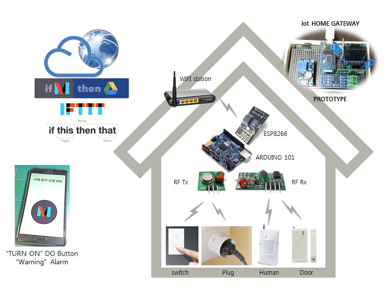
/*
  Cactus Micro Board : Skatch Board choice - LilypadUSB
  pin map reference : http://wiki.aprbrother.com/wiki/Cactus_Micro_Rev2_Hookup_Guide

  (D00)                {interrupt_2}
  (D01)                {interrupt_3}
  (D02) LCD SDA        {interrupt_1}
  (D03) LCD SCL        {interrupt_0}
  (D04)
  (D05) SoftSerial-Rx  - 485 RO (Tx)
  (D06) SoftSerial-Tx  - 485 DI (Rx)
  (D07) Rx from 433MHz {interrupt_4} ??
  (D08)
  (D09)                 485 DE+RF    Tx,Rx Control
  (D10) Tx to 433MHz
  <D11> SoftSerial-Rx - ESP8266_Tx
  <D12> SoftSerial-Tx - ESP8266_Rx
  <D13> ESP8266 CH_PD (HIGH=Enable)
  (D16)
  (D14)
  (D15)
  (D18)
  (D19)
  (D20)
  (D21)

*/

#include <Wire.h>
#include <SoftwareSerial.h>
#include <RCSwitch.h>
#include <ESP8266wifi.h>
#include <livolo.h>
#include <OzOLED.h> //for OLED

const char OK[] PROGMEM = "OK";
const char FAIL[] PROGMEM = "FAIL";
const char ERROR[] PROGMEM = "ERROR";
const char NO_CHANGE[] PROGMEM = "no change";
const char EOL[] PROGMEM = "\n";
const char ready[] PROGMEM = "ready";
const char CONNECT[] PROGMEM = "CONNECT";
const char CWMODE_1[] PROGMEM = "AT+CWMODE=1";
#define DEBUG true

#define SERVER_PORT "80"
#define SSID "YOUR_SSID"
#define PASSWORD "YOUR_PASSWORD"

RCSwitch mySwitch = RCSwitch();
unsigned char rcv_str[9];

Livolo livolo(10); // transmitter connected to pin #10
//my room
//1:remoteID:2*** - key code:8
//2:remoteID:2***- key code:16
//3:remoteID:2*** - key code:56
//4:remoteID:2*** - key code:42

#define S485comm_RX     5  //Serial Receive pin
#define S485comm_TX     6  //Serial Transmit pin

#define Ser485commTxControl 9   //RS485 Direction control

#define RS485Transmit    HIGH
#define RS485Receive     LOW
SoftwareSerial Serial485(S485comm_RX, S485comm_TX); // RX, TX
/*-----( Declare Variables )-----*/
int numLightOn = 0;
int numLightOff = 0;
int numEL_CALL = 0;
unsigned char light1_on[] = {0xF7 , 0x0B , 0x** ,0x** ,0x** ,0x** ,0x** ,0x** ,0x** , 0x00 , 0xB6 , 0xEE};
unsigned char light1_of[] = {0xF7 , 0x0B , 0x** ,0x** ,0x** ,0x** ,0x** ,0x** ,0x** , 0xB5 , 0xEE};

unsigned char light2_on[] = {0xF7 , 0x0B , 0x** ,0x** ,0x** ,0x** ,0x** ,0x** ,0x** , 0x00 , 0xB5 , 0xEE};
unsigned char light2_of[] = {0xF7 , 0x0B , 0x** ,0x** ,0x** ,0x** ,0x** ,0x** ,0x** , 0xB6 , 0xEE};

unsigned char EL_CALL[] =   {0xF7 , 0x0D , 0x** , 0x** ,0x** ,0x** ,0x** ,0x** ,0x** ,0x** ,0x** , 0xA8 , 0xEE};
long int onetimeTimer = 0; // EV1527 usally transmitt several times, this var purpose to ignore it


SoftwareSerial SW_Ser(11, 12);  //11:Rx, 12:Tx
//inPort, outPort, reset_pin, debugPort
ESP8266wifi wifi(SW_Ser, SW_Ser, 4, Serial);//adding Serial enabled local echo and wifi debug
void processCommand(WifiMessage msg);
uint8_t wifi_started = false;


void setup() {
  pinMode(13, OUTPUT);     //only for CactusMicro
  digitalWrite(13, HIGH);  //PIN13 CONNECTED TO CH_PD OF ESP8266, HIGH=ENABLE LOW=Firmware

  pinMode(Ser485commTxControl, OUTPUT);
  digitalWrite(Ser485commTxControl, RS485Receive);  // Init Transceiver

  Serial.begin(9600);      // PC USB     9600
  SW_Ser.begin(9600);
  Serial485.begin(9600);   // set the data rate
  delay(3000);
  //without initial command, sending works!
  mySwitch.enableReceive(4);  // Receiver on inerrupt 0 => <UNO:pin#2> <LilyPad-USB Cactus:pin#3>
  //mySwitch.disableReceive();  //Cactus D10 {interrupt 4}

  mySwitch.enableTransmit(10);
  mySwitch.setPulseLength(149);//320

  OzOled.init();                   //initialze Oscar OLED display
  OzOled.clearDisplay();           //clear the screen and set start position to top left corner
  OzOled.setNormalDisplay();       //Set display to Normal mode
  OzOled.setPageMode();            //Set addressing mode to Page Mode
  //LCD max Cursor size : ( x:0, y:7 ) 16byte string
  LCD_Message(0, 0, "ARDUINO START...");

  SW_Ser.print("+++");  //command for exit from unvarnished transmission mode
  delay(100);
  wifi.writeCommand(CWMODE_1, EOL);
  if (wifi.readCommand(1000, OK, NO_CHANGE) == 0)
    Serial.println("CWMODE_1 FAIL");
  wifi_started = wifi.begin();
  //if (1) { //wifi_started) {
  if (wifi_started) {
    //Serial.println("start to connectToAP");
    if (!wifi.isConnectedToAP())
    {
      Serial.println("start to connectToAP");
      wifi.connectToAP(SSID, PASSWORD);
    }
    else
    {
      Serial.println("already connected to AP, skip connection");
    }

    //SW_Ser.println("AT+CIPMUX=1");
    //wifi.readCommand(2000, OK, NO_CHANGE);
    //SW_Ser.println("AT+CIPSERVER=1,80");
    //wifi.readCommand(2000, OK, NO_CHANGE);

    //Serial.println("connectToAP");
    //wifi.setMUX_1();  //when begin() had HW reset function, it was not working, so I added setMUX again here
    //wifi.startLocalServer(SERVER_PORT);
    //Serial.println("startLocalServer");
    LCD_Message(0, 2, "READY TO RECEIVE");
  } else {
    // ESP8266 isn't working..
    Serial.println("ESP8266 isn't working..");
    LCD_Message(0, 2, "WIFI START FAIL!");
  }
}


void loop() {
  if (mySwitch.available()) {
    long value = mySwitch.getReceivedValue();
    mySwitch.disableReceive();
    delay(1000);
    //Serial.print("Received ");
    if (value == 0) {
      Serial.print("Unknown encoding");
    } else {
      Serial.print("\n\rReceived ");
      Serial.print( value );
      Serial.print(" / ");
      Serial.print( mySwitch.getReceivedBitlength() );
      Serial.print("bit ");
      Serial.print(", Protocol: ");
      Serial.println( mySwitch.getReceivedProtocol() );
    }

    if (value == 5417*** || value == 5417*** || value == 5373***)
    {
      char retry_count = 0;
RESTART:
      Serial.print("\n\rReceived DOOR Sensor!!!");
      delay(5);
      LCD_Message(0, 4, "ROOM1 LAMP1 TGL.");

      //SW_Ser.print("AT+CIPSERVER=0\n");
      //wifi.readCommand(4000, OK, NO_CHANGE);
      SW_Ser.print("AT+RST\n");
      wifi.readCommand(7000, ready, NO_CHANGE,9000);//flush remain buffer and wait for reconnect
      //wait for ESP8266 reconnect AccessPoint again. it takes some time
      retry_count = 0;
      while (!wifi.isConnectedToAP())
      {
        Serial.println("\n\rstart to connectToAP");
        wifi.connectToAP(SSID, PASSWORD);
        retry_count++;
        if (retry_count >= 4) break;
      }

      SW_Ser.print("AT+CIPMUX=0\n");
      wifi.readCommand(2000, OK, NO_CHANGE, 2000);

      retry_count = 0;
      do
      {
        SW_Ser.print("AT+CIPSTART=\"TCP\",\"maker.ifttt.com\",80\r\n");
        retry_count++;
        if (retry_count >= 4) break;
      } while ( wifi.readCommand(2000, CONNECT, OK,1000) != 1 );


      SW_Ser.print("AT+CIPMODE=1\r\n");  //unvanished mode, transparent mode

      if (wifi.readCommand(2000, OK, NO_CHANGE) == 1)
      {
        Serial.print("\n\r (1/3) Set Transparent Tx Mode\n\r");
        wifi.readCommand(2000, OK, OK,2000);//flush remain buffer
      } else
      {
        Serial.print("\n\r (1/3) Error!! Set Transparent Tx Mode\n\r");
      }

      SW_Ser.print("AT+CIPSEND\r\n");
      char result = wifi.readCommand(3000, OK, ERROR);
      if (result == 2) goto RESTART;
      Serial.print("\n\r (2/3) start Stream Sending\n\r");

      delay(100);
      Serial.println("\n\r[send trigger : event1]");

      SW_Ser.println("GET /trigger/front_door_open/with/key/*************nU74P HTTP/1.1");
      SW_Ser.println("Host: maker.ifttt.com");
      SW_Ser.println("Accept: */*");
      SW_Ser.println("User-Agent: Mozilla/4.0 (compatible; esp8266 Lua; Windows NT 5.)");
      SW_Ser.println("");

      wifi.readCommand(3000, OK, OK);//flush receive buffer
      //Serial.println("\n\r[exit from unvarnished transmission mode]");
      SW_Ser.print("+++");
      wifi.readCommand(3000, OK, OK);//flush receive buffer
      Serial.println("\n\r[close TCP port]");
      SW_Ser.print("AT+CIPCLOSE\r\n");
      wifi.readCommand(10000, OK, NO_CHANGE); //flush receive buffer

      Serial.print("ROOM1 LAMP1 TGL.!!!");

      SW_Ser.println("AT+CIPMUX=1");
      wifi.readCommand(5000, OK, NO_CHANGE);
      SW_Ser.println("AT+CIPSERVER=1,80");
      wifi.readCommand(2000, OK, NO_CHANGE);
      mySwitch.enableReceive(4);
    }
    mySwitch.resetAvailable();
  }
}

void LCD_Message(byte X, byte Y, String msg)
{
  OzOled.setCursorXY(X, Y);
  OzOled.printString((const char*)msg.c_str());
}
_baVEVgguW1.jpg?auto=compress%2Cformat&w=48&h=48&fit=fill&bg=ffffff)


Comments
Please log in or sign up to comment.