


Hardware components | ||||||
| × | 1 | ||||
| × | 1 | ||||
| × | 1 | ||||
| × | 1 | ||||
 |
| × | 1 | |||
| × | 1 | ||||
| × | 1 | ||||
| × | 1 | ||||
| × | 1 | ||||
| × | 1 | ||||
Hand tools and fabrication machines | ||||||
| ||||||
| ||||||
| ||||||
In this project, TSOP (IR Receiver) is connected with Arduino. Arduino receives encoded signal coming from IR Remote and then decodes by using IRremote.h library, which is easily available on internet (Find this library by typing on Google IR remote library for Arduino). After decoding the signal, compare decoded signal with defined value, if the match occurs then perform related function or switching on/off related relay by using digital input/output. Here AC load is used for demonstration.
Three Home/Office Appliances are used for demonstration. In which one zero watt bulb indicated by light 1 and second is 100 watt bulb indicated by light 2 and third and last is TV/LCD indicated by TV.
LCD is also interfaced with arduino in this system for displaying the current status of Appliances like TV ON, TV OFF, light 1 ON, light 1 OFF, light 2 ON, light 2 OFF, ALL ON, ALL OFF etc.
Fig. 1: Image showing IR Remote used for controlling Home Automation System
Fig. 2: Prototype of Arduino based IR Remote controlled Home Automation System
Fig. 3: Image showing switching a bulb on by IR Remote via Home Automation System
Fig. 4: Image showing display panel in prototype of Arduino based Home Automation System
Block Diagram of Arduino based IR Remote controlled Home Automation System
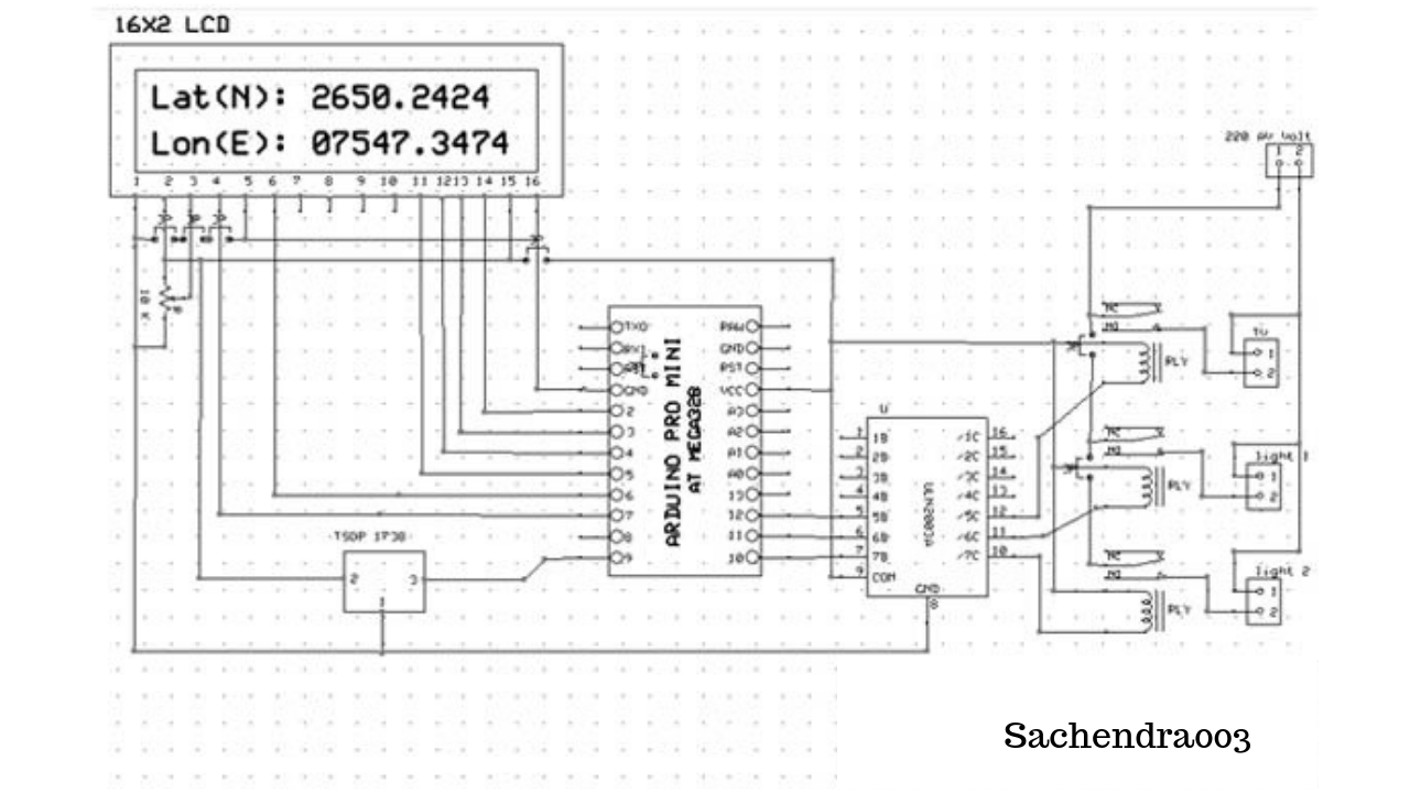
Circuit of this system is very simple in this TSOP 1738 connected to digital pin 9 of Arduino, which detects 38 KHz IR frequency and relays are connected to digital pin 10, 11, 12 of Arduino for controlling light 1, light 2, TV respectively using ULN 2003 IC is a high-voltage high-current Darlington transistor arrays.
Each consists of seven NPN Darlington pairs that feature high-voltage outputs with common-cathode clamp diodes for switching inductive loads and 5 volt relays are used here, which are best suitable for these types of Projects.
Light 1 is connected with relay 1, light 2 is connected with relay 2 and TV is connected with relay 3.
Circuit Diagram of TSOP1738 based IR Receiver
Relay Connection Circuit for DC supply (connect AC supply in place of battery and electrical appliances in place of LED polarity does not effects in AC.)
You can add more Home/Office Appliances with this system by adding some functions in the program. 16x2 LCD’s commands pins RS and EN is directly connected with pin 7 and 6 respectively and Data pins d4, d5, d6, d7 are connected with 5, 4, 3, 2 pins of Arduino.
Working1. When we press key 1, this is responsible for tuning on TV/LCD and if we again press this, key is now responsible for tuning off TV.
2. When we press key 2 this is responsible for tuning on light 1 and if we again press this key it is now light 1 tuned off.
3. When we press key 3 this is responsible for tuning on light 2 and if we again press this key it is now light 2 tuned off.
ProgrammingProgramming of this project is very easy. Initialize IR Remote library and LCD Library Then define some strings for match or compare. Store IR decoded result and compare this with defined strings. If any match occurs perform related function then enjoy it.
Components Used
1. Arduino Pro Mini
2. TSOP 1738
3. Connecting wires
4. Power supply
5. AC appliances
6. Resisters
7. Capacitors
8. IR remote
9. Relays
10. ULN2003


Comments
Please log in or sign up to comment.