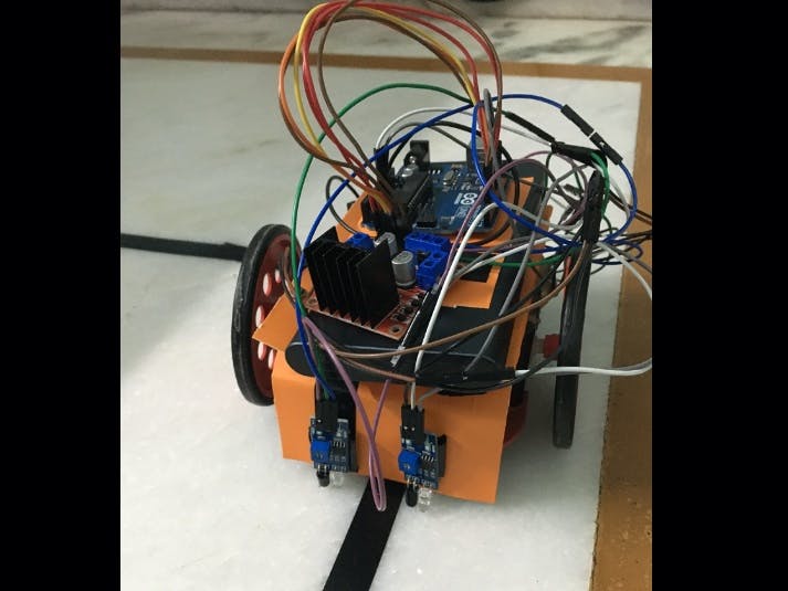
The concept of working of a line follower robot is based on the phenomenon of light. We know that white colour reflects almost all of the light that falls on it, whereas black colour absorbs most of the light. In case of a line follower robot we use IR transmitters and receivers also called photodiodes. They are used for sending and receiving light. IR transmits infrared lights. When infrared rays falls on white surface, it’s reflected back and catched by photodiodes which generates some voltage changes. When IR light falls on a black surface, light is absorb by the black surface and no rays are reflected back, thus photo diode does not receive any light or rays.
Here in this Arduino line follower robot when sensor senses white surface then Arduino gets 1, ie, HIGH as input and when senses black line arduino gets 0, ie, LOW as input.
Circuit connections for IR Proximity Sensors:
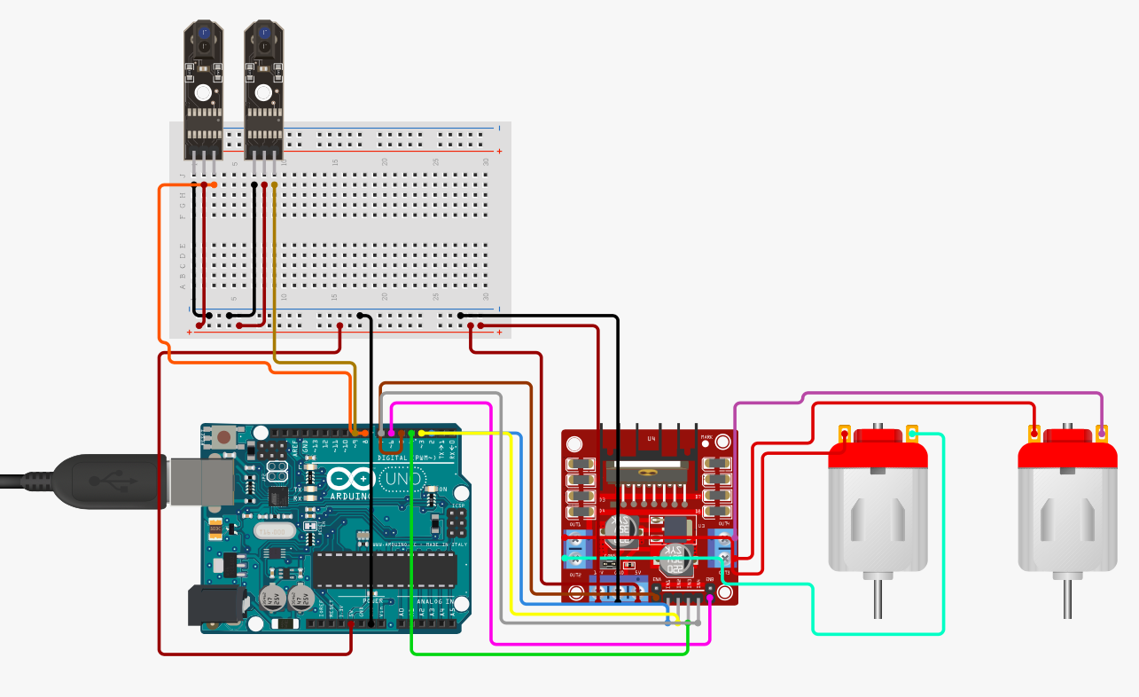
- The IR sensor is a 3 three wired sensor, in which the brown and the black wire are used to connect the sensor to the power supply, whereas, the red wire is connected to the load, or Arduino, in our circuit.
- The load wires of the IR sensors are connected to pin 8, 9 and 10 as shown in the schematic.
The H-Bridge Motor Drivers L298N is used to drive DC motors as they require much more current that the arduino can provide.
The L298N motor controller follows the H-bridge configuration, which is handy when controlling the direction of rotation of a DC motor. The other benefit of using an H-bridge is that we can provide a separate power supply to the motors. This is very significant especially when using an Arduino board where the 5V power source is simply not enough for two DC motors.
We have Motor A and Motor B terminals. These connect to the microcontroller. Motor A connects to terminals 1 and 2 while Motor B connects to terminals 3 and 4.
If we want the left motor to rotate in one direction, we apply a high pulse to IN1 and a low pulse to IN2. To reverse the direction, reverse the pulses to IN1 and IN2. The same applies to the right motor.
If we want the left motor to rotate in one direction, we apply a high pulse to IN1 and a low pulse to IN2. To reverse the direction, reverse the pulses to IN1 and IN2. The same applies to the right motor.
Speed control is also possible with the L298N motor driver. All we need is feed PWM ( Pulse Width Modulation) signals to the motor enable pins. The speed of the motor will vary according to the width of the pulses. The wider the pulses, the faster the motor rotates. In Arduino this can be done using analogWrite(pinNumber, duration). Pins on Arduino with ‘~’ support PWM.
Circuit connections forL298N H-Bridge Motor Driver :
- Motor A wires are connected to motor terminal 1 and 2 of L298N, whereas Motor B wires are connected to motor terminal 3 and 4. IN1, IN2, IN3 and IN4 are connected to pin 2, 3, 4, 7 respectively.
- Now, Motor A and Motor B Enable should be connected to terminals on arduino which have ~ sign, so that speed of these motors can be controlled using PWM. Here, they have been connected to pin 5 and 6.
- Other connections are clear from the schematic.
Step 1: Connect the circuit as shown in the schematic.
Step 2: Use the Arduino IDE to write your own code.
Step 3: Upload your code to the Arduino and connect it to the batteries or you can even use a power bank to run the Arduino.
Step 4: Test it on a black path.


_ztBMuBhMHo.jpg?auto=compress%2Cformat&w=48&h=48&fit=fill&bg=ffffff)


_3u05Tpwasz.png?auto=compress%2Cformat&w=40&h=40&fit=fillmax&bg=fff&dpr=2)
Comments
Please log in or sign up to comment.