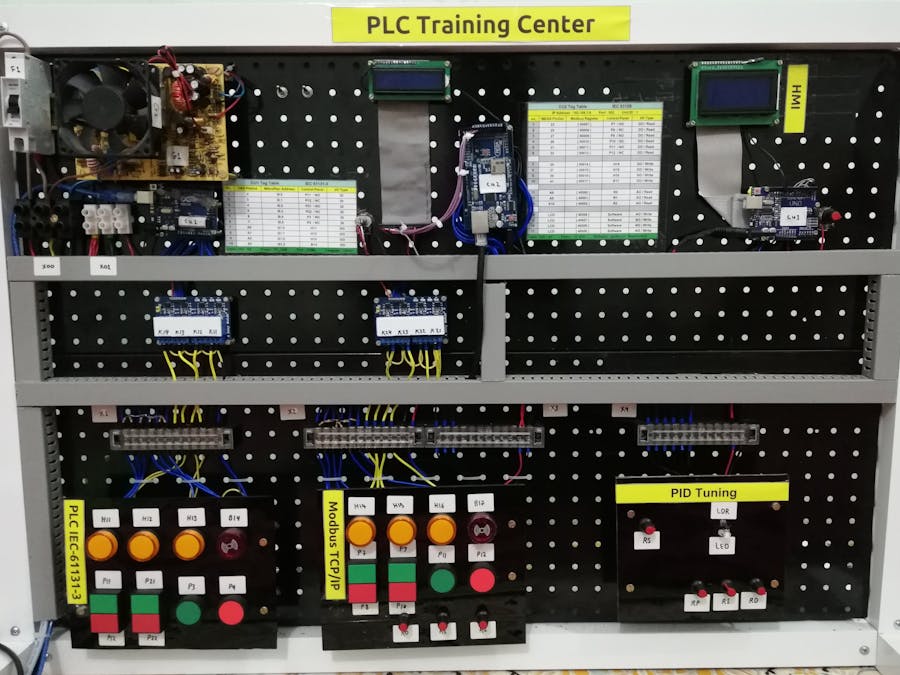
Before you decide to built the same project please collect the information about (PLC, Modbus, PID, HMI, Wiring diagram)
So I'm not gonna explain that stuff because that is a concept of System Automation Process.Abstract
There are many useful PLC kits in the market if you talk about the real one, But you can built it with Arduino board, so I will give you all the wiring diagram and software you need to build this.
There are 3 main control units: CU1 = (PLC), CU2 = (Modbus TCP/IP), CU3 = (PID), so this kit will be proper thing for student or amateur guys in the automation world. All three CU are separated so I'm use different software for each of theme:
CU1 = MikroPlan
CU2 = You can use any of the following Modscan, ModbusPoll, Factory IO
CU3 = Compact PID, just need flow the HMI and light indicator
Project Playlist "YouTube"Demo Videos
All Videos:
How I Built It?You will see the image for all the process from the beginning:
First of all you must:
Follow the wiring diagram in schismatic part below.
And if you get confused in any part, you just check the play list I specially made for this project in English language.
And you can ask I will be appreciate to answer you questions
My accounts:
https://www.facebook.com/essoselectronic
https://www.youtube.com/c/essoselectronic
HardwareTypes of Arduino I'm use:
- Arduino UNO for ladder (Prefer to be the original one)
- Arduino MEGA and Ethernet shield (Prefer to be MEGA) "you can use UNO but may have some crashes in some time"
- For PID you can use any board you need
Any CNC will be a good choice for a best results (swipe the images below)
That is a good idea for easy instillation the components on it
I prefer to use terminals and then put a tag and numbers on it so the student can learn to flow the wiring
Please solder any thing that need soldering instead of using bread board for more robustness
Look what I've done by mistake I solder the top potentiometer in reverse so that guy will work revers of the others
Just use the drill and screws with screw driver
For terminal use wiring bullets that's give your project a good look
be careful PLZ
Don't forget to use 10k Ohm pull-up resistor for push buttons
Power supplyI use the PC power supply cause its reliable and have two differents DC voltages that's I need. +5VDC & +12VDC
Or
You can use only a 12 VDC power source and 5 volt regulator, No problem.
Put all things together
Try to test all projects part before you tight up
According to the wiring diagram
For CU1 and CU2
I explained it in the YouTube playlist
The developer page:
Other Arduino PLC software:
I put this IP in the code : 192.168.1.8
port : 502
Modbus ID : 1
Change your PC IP to the : 192.168.1.9
The software I prefer Modscan because its wildly use and easy and you can try to use modbus-poll or if you have a curiosity about 3D simulation you can download the factory IO


_wzec989qrF.jpg?auto=compress%2Cformat&w=48&h=48&fit=fill&bg=ffffff)
_ztBMuBhMHo.jpg?auto=compress%2Cformat&w=48&h=48&fit=fill&bg=ffffff)


_3u05Tpwasz.png?auto=compress%2Cformat&w=40&h=40&fit=fillmax&bg=fff&dpr=2)
Comments
Please log in or sign up to comment.