This project implements the FOC of PMSM (using sensors) in hardware. I made this project for my M.tech project work.
Variable speed motor drives are being rapidly employed for variety of applications in order to make the system more efficient. Permanent Magnet Synchronous Motors are capable of providing high torque to current ratios, high power to weight ratios, high efficiency and robustness. Due to these benefits, PMSM are widely used in modern variable speed AC drives, especially in electric vehicle (EV) and hybrid EV applications. Also, due to easily available digital signal processors, there is a boost in the digital control market in the field of motor and power control.
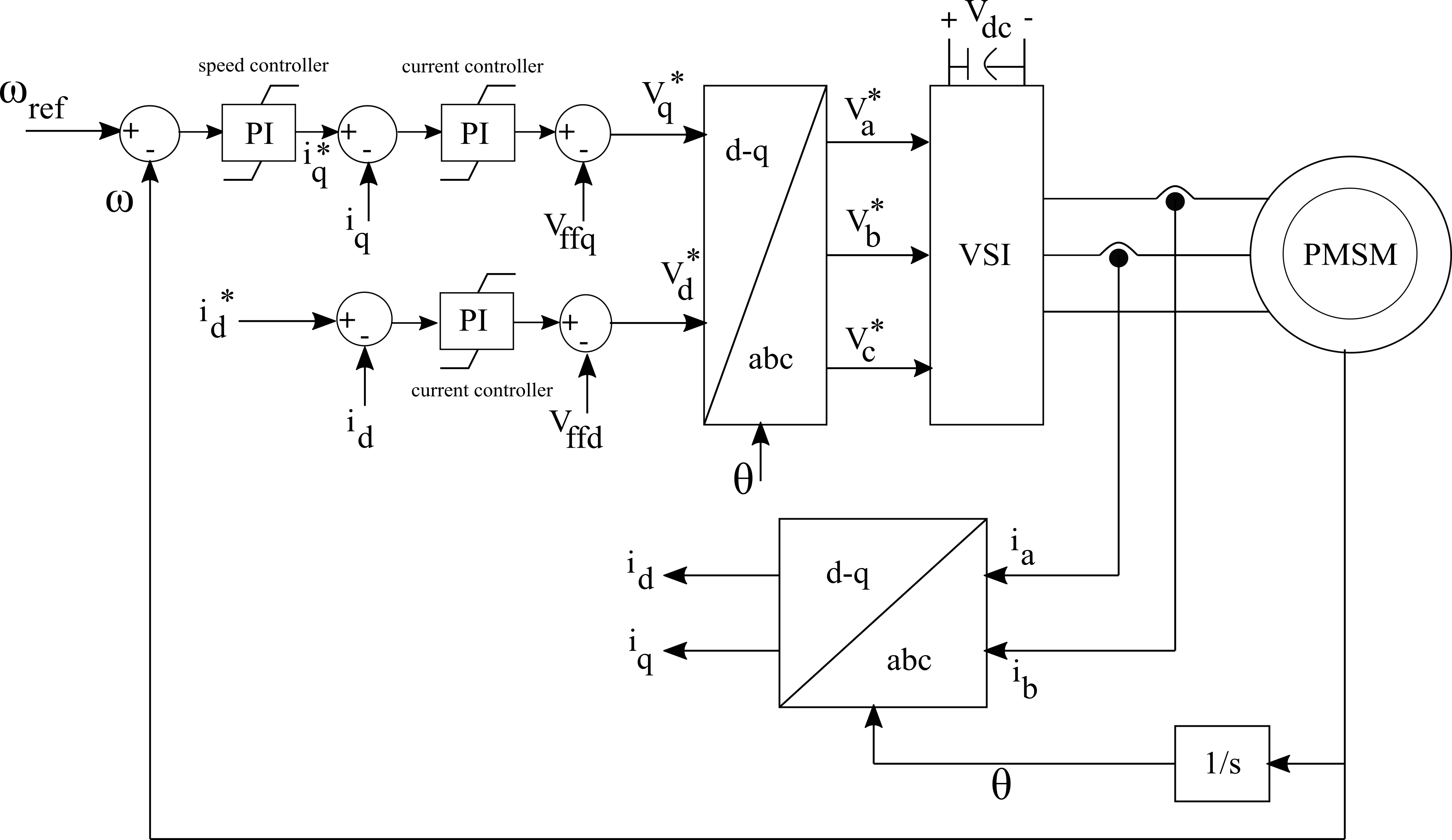
The basic block diagram of FOC is shown in the figure.
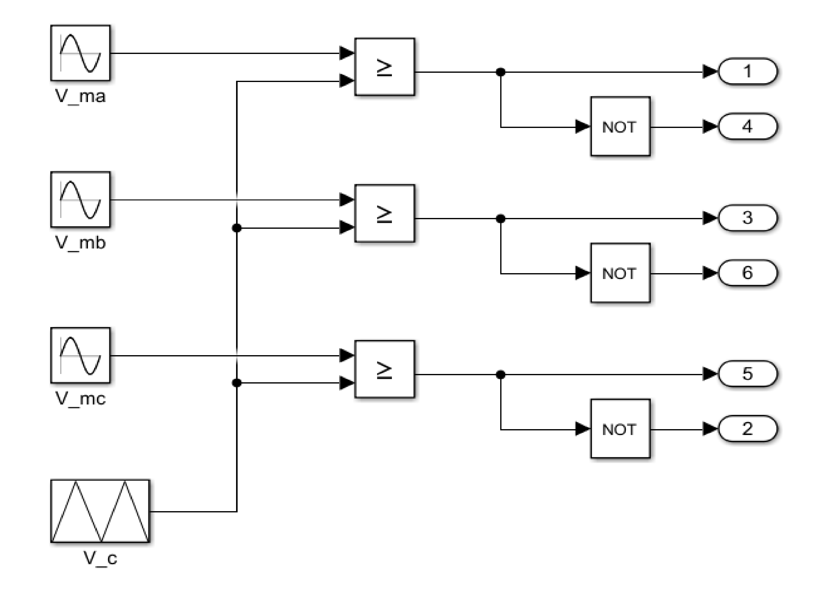
In the above control, the error between reference speed and actual sensed speed is fed to the speed PI controller which generate iq reference as its output. The currents flowing in the stator windings of PMSM are sensed and converted to d-q reference frame using θ (obtained from speed sensor after integrating). These currents iq and id are compared with their reference components and the error is send to their respective current PI controller which generates vq and vd reference (approximately). From eqn (3.9) and (3.10) it can be observed that there are cross coupling terms in both the equations i.e. the vd equation contains the term containing iq and the vq equation contains the term containing id. The feed forward terms are added or subtracted (as per required)to the current controller output to obtain vq and vd reference. Using Clarke’s and Park’s transformation the three reference vectors are generated and using PWM techniques the pulses are fed to the inverter whose output supplies the motor.
The hardware setup is shown in the figures below:


Comments
Please log in or sign up to comment.