


Hardware components | ||||||
| × | 1 | ||||
| × | 1 | ||||
| × | 2 | ||||
| × | 1 | ||||
| × | 1 | ||||
| × | 1 | ||||
Software apps and online services | ||||||
 |
| |||||
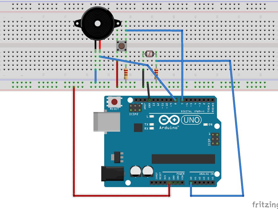
In this tutorial, you will learn how to build a rooster alarm that activates a piezo buzzer when the light level in the environment increases beyond a certain threshold. The alarm can be reset by pressing a button. The current light level will be displayed in real-time via the Serial Monitor.
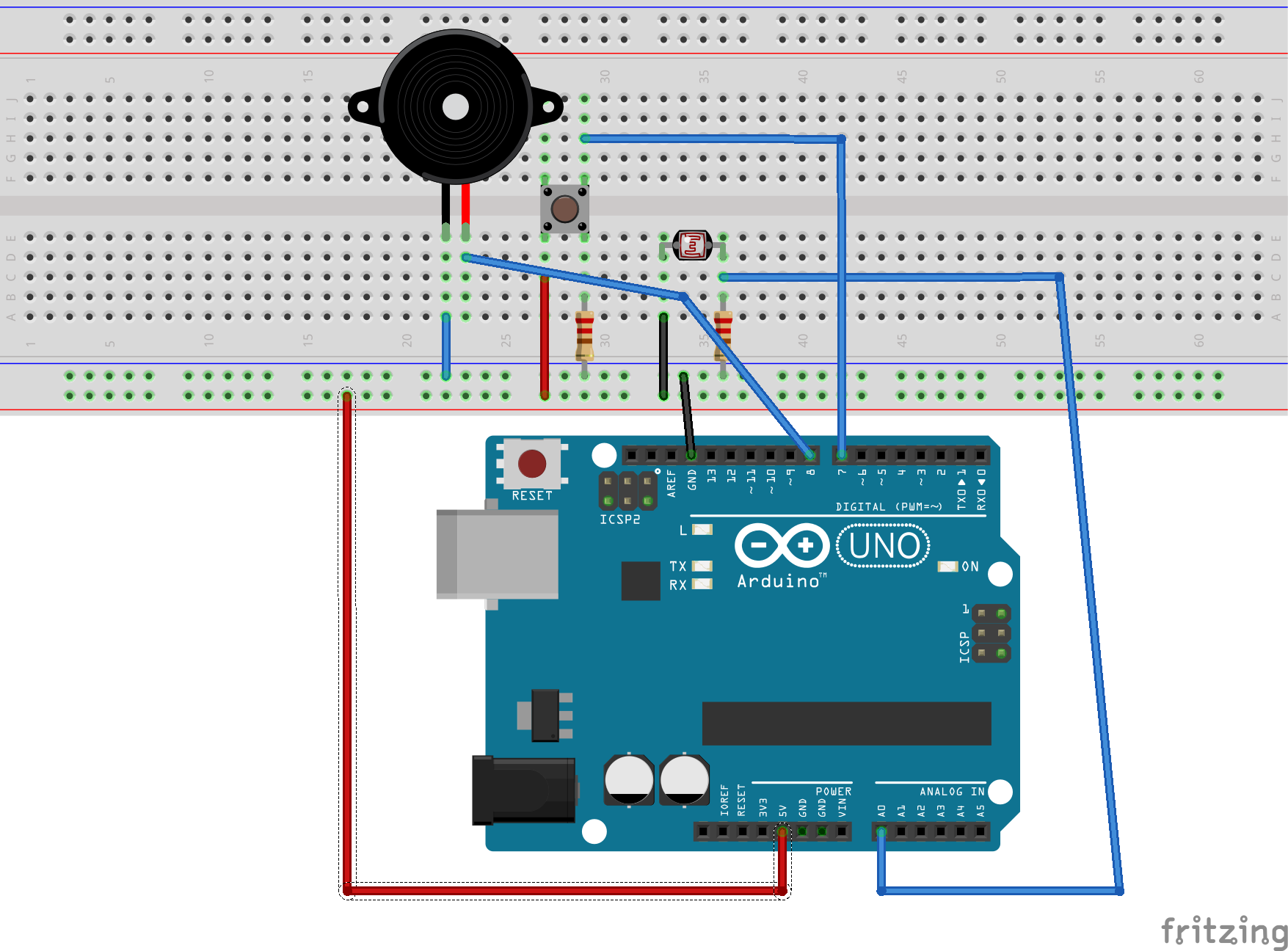
Here are the simplified and professional connection instructions for the rooster alarm project:
1. **Light Detector (Photoresistor) Connections:**
- Connect one end of the photoresistor to the Arduino 5V pin.
- Connect the other end of the photoresistor to a node with a 10k resistor and a wire leading to Arduino analog pin A0.
- Connect the other end of the 10k resistor to the Arduino GND pin.
2. **Piezo Buzzer Connections:**
- Connect the negative terminal of the piezo buzzer to the Arduino GND pin.
- Connect the positive terminal of the piezo buzzer to Arduino digital pin 9.
3. **Push Button Connections:**
- Connect one terminal of the push button to the Arduino 3.3V pin.
- Connect the other terminal of the push button to a node with a 10k resistor and a wire leading to Arduino digital pin 7.
- Connect the other end of the 10k resistor to the Arduino GND pin.
Programconst int DirectSunlightCutOff = 1023;
const int BrightLightCutOff = 900;
const int MediumLightCutOff = 525;
const int LowLightCutOff = 310;
const int VeryLowLightCutOff = 200;
const int NightCutOff = 100;
int DetectorPin = A0;
int RawValue = 0;
int BuzzerPin = 9;
int BuzzerFreq = 300;
int BuzzerFreqRange = 400;
int NumberRoosterCalls = 5;
int RoosterCallsFinished = false;
int ButtonPin = 7;
boolean AlarmTripped = false;
void setup()
{
Serial.begin(9600);
Serial.println("Rooster Alarm ...");
}
void PrintBrightnessLevel(int value)
{
Serial.print("BrightnessLevel: ");
if (value <= NightCutOff)
{
Serial.print("Night");
}
else
if (value <= VeryLowLightCutOff)
{
Serial.print("Very Low Light");
}
else
if (value <= LowLightCutOff)
{
Serial.print("Low Light");
}
else
if (value <= MediumLightCutOff)
{
Serial.print("Medium Light");
}
else
if (value <= BrightLightCutOff)
{
Serial.print("Bright Light");
}
else
{
Serial.print("Direct Sun Light");
}
}
void RoosterCall()
{
for (int i = 0; i < NumberRoosterCalls;
i++)
{
for (int j = 0; j < BuzzerFreqRange;
j++)
{
tone(BuzzerPin, BuzzerFreq + j);
delay(10);
}
}
noTone(BuzzerPin);
RoosterCallsFinished = true;
}
void ResetSoundConfirmation()
{
for (int i = 0; i < 5; i++)
{
tone(BuzzerPin, BuzzerFreq);
delay(100);
noTone(BuzzerPin);
delay(100);
}
}
void loop()
{
// Read Reset Button
RawValue = digitalRead(ButtonPin);
if (RawValue == 1)
{
ResetSoundConfirmation();
AlarmTripped = false;
RoosterCallsFinished = false;
}
RawValue = analogRead(DetectorPin);
PrintBrightnessLevel(RawValue);
Serial.print(" , RawValue: ");
Serial.println(RawValue);
if (RawValue >= VeryLowLightCutOff)
{
AlarmTripped = true;
}
if (AlarmTripped && !RoosterCallsFinished)
{
RoosterCall();
}
}I have determined that direct sunlight is between 900 and 1023:
const int DirectSunlightCutOff = 1023;Bright light from 525 to 900 was determined:
const int BrightLightCutOff = 900;Medium-light from 310 to 525 was determined:
const int MediumLightCutOff = 525;Low lighting between 200 and 310 was determined:
const int LowLightCutOff = 310;Very low lighting between 100 and 200 was determined:
const int VeryLowLightCutOff = 200;Nighttime lighting between 0 and 100 was determined:
const int NightCutOff = 100;The node consisting of the light detector and the 10-k resistor, which measures the voltage of the light levels is assigned to the Arduino analog pin A0:
int DetectorPin = A0;The RawValue variable contains the read data from the light detector to 0:
int RawValue = 0;The buzzer is assigned to digital pin 9 of the Arduino:
int BuzzerPin = 9;The frequency of the sound generated by the buzzer is set to 300 hertz:
int BuzzerFreq = 300;The buzzer pitch range for the rooster call alarm is 400 hertz:
int BuzzerFreqRange = 400;When the sun comes up, the number of "rooster calls" to sound is 5:
int NumberRoosterCalls = 5;If the variable RoosterCallsFinished does, the alarm, or "rooster, " has ended its five "rooster calls, " and the alarm stops. It is initialized to false to indicate that the sun has not yet triggered the alert:
int RoosterCallsFinished = false;The push button is assigned to digital pin 7 of the Arduino:
int ButtonPin = 7;The AlarmTripped variable is true if the sun has risen and the alarm has been tripped; otherwise, it is false:
boolean AlarmTripped = false;The setup() function initializes a communication speed of 9, 600 bauds for the Serial Monitor and prints a text message to indicate the start of the program.
void setup()
{
Serial.begin(9600);
Serial.println("Rooster Alarm ...");
}PrintBrightnessLevel() prints a text message on the Serial Monitor that shows the level of light based on the light detector read value. The value read from the light sensor is compared to a number of "cut-off" values indicating the end of the range for that light level. The NightCutOff value, for example, is the highest value for the level of night light.
void PrintBrightnessLevel(int value)
{
Serial.print("BrightnessLevel: ");
if (value <= NightCutOff)
{
Serial.print("Night");
}
else
if (value <= VeryLowLightCutOff)
{
Serial.print("Very Low Light");
}
else
if (value <= LowLightCutOff)
{
Serial.print("Low Light");
}
else
if (value <= MediumLightCutOff)
{
Serial.print("Medium Light");
}
else
if (value <= BrightLightCutOff)
{
Serial.print("Bright Light");
}
else
{
Serial.print("Direct Sun Light");
}
}In the variable NumberRoosterCalls, the RoosterCall() feature sounds the number of "rooster calls." A "rooster call" simulates the real sound of a rooster when the sun rises and the pitch of the sound increases with the buzzer. The buzzer sounds are finished after all "rooster calls" have been completed.
void RoosterCall()
{
for (int i = 0; i < NumberRoosterCalls;
i++)
{
for (int j = 0; j < BuzzerFreqRange;
j++)
{
tone(BuzzerPin, BuzzerFreq + j);
delay(10);
}
}
noTone(BuzzerPin);
RoosterCallsFinished = true;
}The ResetSoundConfirmation() function causes the buzzer to emit a number of sounds indicating that five times the alarm reset button has been pressed:
1. Emitting a tone using the buzzer.
2. Holding this tone for 100 milliseconds.
3. Stopping the tone from being emitted by the buzzer.
4. Suspending program execution for 100 milliseconds.
void ResetSoundConfirmation()
{
for (int i = 0; i < 5; i++)
{
tone(BuzzerPin, BuzzerFreq);
delay(100);
noTone(BuzzerPin);
delay(100);
}
}ResetSoundConfirmation() caused the buzzer to emit several sounds that the alarm reset button was pressed five times:
1. Reading the status of the reset button.
2.When pressing the button, the function causes a buzzer to emit the reset sound sequence and to reset the alarm so that the light level in the environment can again trigger this function.
3. Reading in the light level from the light detector.
4. Printing out the light level description to the Serial Monitor by calling the PrintBrightnessLevel() function.
5. Printing out the raw numerical value of the light level to the Serial Monitor.
6. If the level of light is greater or equal to low light, which means that the sun rises, the function will trigger the alarm. This means that the light level is higher or equal to VeryLowLightCutOff and therefore the light level is lower or higher.
7. If the alarm has been tripped and the “rooster call” sound effects have not been completed, then the function starts the “rooster call” sound effects by executing the RoosterCall() function.
void loop()
{
// Read Reset Button
RawValue = digitalRead(ButtonPin);
if (RawValue == 1)
{
ResetSoundConfirmation();
AlarmTripped = false;
RoosterCallsFinished = false;
}
RawValue = analogRead(DetectorPin);
PrintBrightnessLevel(RawValue);
Serial.print(" , RawValue: ");
Serial.println(RawValue);
if (RawValue >= VeryLowLightCutOff)
{
AlarmTripped = true;
}
if (AlarmTripped && !RoosterCallsFinished)
{
RoosterCall();
}
}


Comments
Please log in or sign up to comment.