
Software apps and online services | ||||||
 |
| |||||
Hand tools and fabrication machines | ||||||
 |
| |||||
 |
| |||||
Introduction: LED blinking is often the "Hello, World!" of embedded systems development. It serves as a fundamental exercise for beginners to understand the basics of microcontroller programming. In this blog post, we'll delve into the process of LED blinking on the STM32 BlackPill development board using CubeIDE, a powerful Integrated Development Environment (IDE) provided by STMicroelectronics.
What is STM32 BlackPill? The STM32 BlackPill is a popular development board featuring an STM32 microcontroller from STMicroelectronics. It offers an affordable and versatile platform for embedded systems development, equipped with various peripherals and GPIO pins for interfacing with external components.
Getting Started with CubeIDE: CubeIDE is an Eclipse-based IDE developed by STMicroelectronics specifically for STM32 microcontrollers. It provides a comprehensive set of tools for code development, debugging, and project management.
To get started, download and install CubeIDE from the official STMicroelectronics website. Once installed, launch CubeIDE and create a new STM32 project targeting the STM32 microcontroller on the BlackPill board.
Configuring GPIO: LED blinking involves toggling the state of a GPIO pin connected to an LED. In CubeIDE, configuring GPIO pins is straightforward:
- Open the Pinout & Configuration tab.
- Select the GPIO pin connected to the onboard LED (usually PC13).
- Set the Pin Mode to Output push-pull.
- Apply the changes.
Writing the Blinking Code: CubeIDE generates a basic project structure with the necessary startup code and configuration files. Now, let's write the code to toggle the LED state at regular intervals:
HAL_GPIO_WritePin(GPIOC, GPIO_PIN_5, 0);
		  HAL_Delay(1000);
	      HAL_GPIO_WritePin(GPIOC, GPIO_PIN_5, 1);
		  HAL_Delay(1000);
This code initializes the GPIO pin connected to the LED as an output and toggles its state in a continuous loop with a delay of 500 milliseconds between each toggle.
Building and Flashing the Project: After writing the code, build the project in CubeIDE. This process compiles the code and generates the binary file (.bin) ready for flashing onto the STM32 BlackPill board.
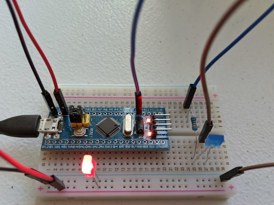
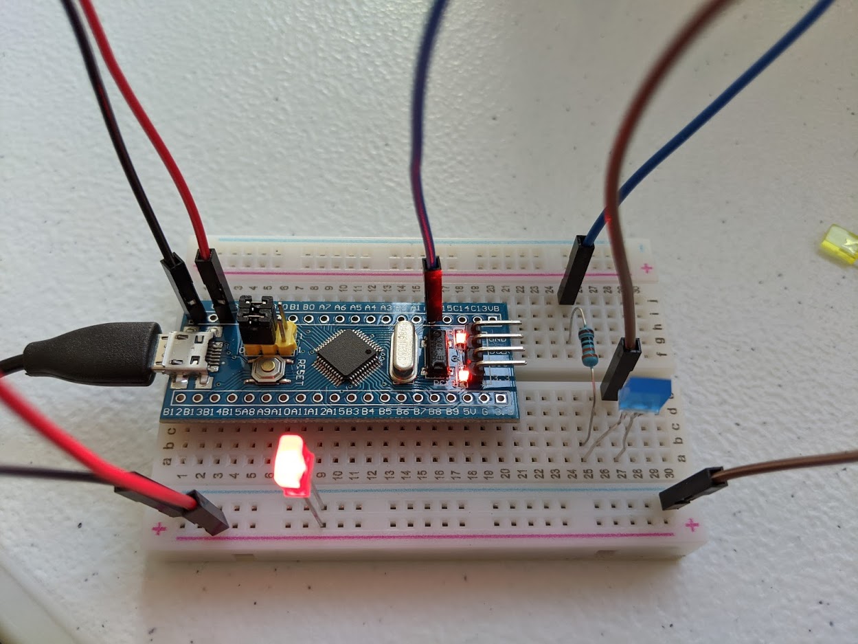
Connect the BlackPill board to your computer using a USB-to-Serial adapter and ensure that the necessary drivers are installed. Then, select the appropriate debug configuration and flash the binary onto the board using CubeIDE's built-in debugger.
Conclusion: In this blog post, we explored the process of LED blinking on the STM32 BlackPill development board using CubeIDE. By following the steps outlined above, beginners can gain a solid understanding of microcontroller programming fundamentals and get started with embedded systems development on the STM32 platform.LED blinking is just the beginning; from here, you can explore more advanced features and peripherals to create complex embedded applications.


Comments