Previously, I did this story on how to use sensors on a Ripple LoRa mesh network: https://www.hackster.io/scottpowell69/easy-lora-mesh-sensors-2ddc33
Now, I have added a new firmware type for controlling various actuators remotely. These can be either on/off switches, dimmers, servos, or anything that takes a PWM signal.
You can wire up to 4 separate devices per node, which can be any combination of digital on/off switches, or PWM controlled devices.
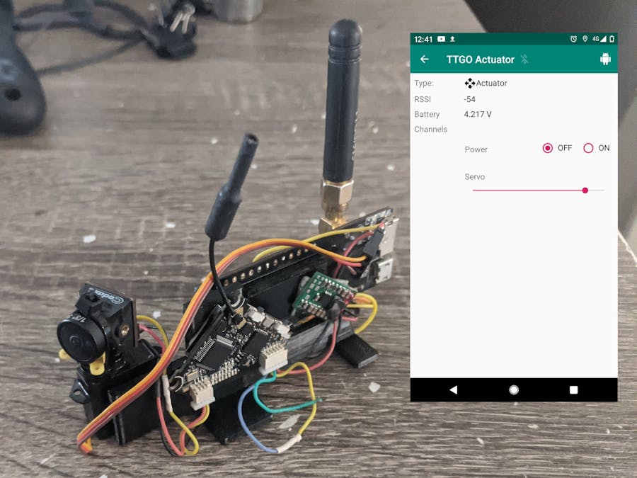
A DemonstrationI whipped up this little test using the TTGO board with a hobby FPV camera and transmitter, along with a small hobby servo.
Here I have two device channels configured via the Commander app:
Channel A: is type Switch, and switches a Polulu 5V step up/down regulator, with the SHDN connected to TTGO's pin 12.
Channel B: is type Servo, and is powered off the Polulu, with signal wire to TTGO's pin 13.
The FPV camera and video transmitter both run off the 5V supply from the Polulu regulator. So, my channel A turns both the servo and the camera/transmitter on. Channel B lets me look left/right. Here is a video demonstration:
(Also, my phone is connected via Bluetooth to the Home radio, which is just off camera)
Flashing the firmwareThe firmware is downloadable from the Ripple GitHub site here: https://github.com/spleenware/ripple
For the TTGO V2, currently the only board supported for this setup, you need to use these firmware images:
for your Home node: RippleV5-USB-TTGOV2.binorRippleV5-Bluetooth-TTGOV2.bin
for the actuator nodes: RippleActuator-TTGOV2.bin
The GitHub readme has instructions for flashing to the ESP32 boards.
With the TTGO connected via USB cable to your computer, you can test that the firmware was flashed OK by opening the Serial Monitor in the Arduino IDE (set to 9600 baud). Enter 'q' (without quotes) in the send line, and press enter. The serial monitor should reply with text starting with "Q:..."
Configuring the deviceThe app has two launcher icons. The one labelled 'DeviceProvision' is for when you are setting up new nodes, or modifying preferences or settings. The main one labelled 'RippleCommander' is for when you connect the Home device and monitor or interact with the nodes currently deployed.
Each of the nodes in the network must be assigned a unique number, from 2..254. Node id 1 is reserved for the Home node (this is the one you connect to your Android, when in the main Commander screens).
The Home node does not need any configuring once it has been flashed. Each time you connect to your Android it will download all the current configuration.
The actuator nodes need to be initially configured, just the once, in the DeviceProvision screen. Connect the TTGO via USB-OTG cable to your Android, then accept the Android system permission that pops up, asking if its ok to use the USB peripheral. A popup should appear asking if it's OK to Add the New Device. Accept, and in the Device Setup screen you need to assign the ID and display name. Then click 'Save'.
There is also a '...' button to the right for more specific configuration. Click on this, to see this screen:
Here you use the 'More' button to configure up to 4 different 'channels': A, B, C, D. You can modify the labels to something more meaningful, like 'Green LED' above.
Each channel has a Type, selectable from the drop-downs. At present Servo(X) and Servo(Y) are the handled the same, but in a future release the UI will be improved for a RC-style gimbal to control two servos. Some notes about the types:
Switch: the pin will be a simple digital pin, pulled LOW or HIGH.
Button: the pin will be a digital pin, but pulsed HIGH for 200ms, then LOW.
Servo: the pin will be a PWM pin, the slider value is mapped from 1 millisecond to 2 milliseconds (middle is 1.5 milliseconds). Uses 50Hz frequency.
RawPWM: again a PWM pin, but uses 8-bit resolution, and the slider is mapped to the whole range, ie 0 to 255. eg. for dimming an LED.
(The four channels are mapped to pins 12, 13, 14, 15 on the TTGO.)
Once you are finished defining your Channels, click on SAVE in the toolbar. Then, in the next screen tap on the 'Save' button near the bottom. This should then change to a 'Program' button. Click on this to then configure the actuator node with the channels, id, etc.
Controlling your stuff out in the wildOnce your actuator node is out there, you connect your Home radio in the main Commander screen, then in the main list of nodes, tap on your Actuator node to see the info screen:
Like other nodes, you can see the current battery voltage and the signal strength. The Channels section will vary, depending on the channels you configured in the above section. But here, you can see things like Switches, sliders and buttons.
When you change a channel's state, you will notice the whole panel gets a grey overlay which temporarily disables the UI. Once the node responds with an acknowledgement, the overlay disappears and the buttons and sliders are updated.
FeedbackThere are endless possibilities with this new firmware. You could have it open or close a gate at a far end of your property, or turn lights on and off, etc. Is only limited by your imagination. Feel free to message me here if you have questions.
Enjoy!
Regards,
Scott Powell


Comments
Please log in or sign up to comment.