

Hardware components | ||||||
| × | 1 | ||||
 |
| × | 1 | |||
| × | 1 | ||||
| × | 1 | ||||
| × | 1 | ||||
 |
| × | 1 | |||
| × | 1 | ||||
| × | 1 | ||||
Software apps and online services | ||||||
| ||||||
| ||||||
Hand tools and fabrication machines | ||||||
 |
| |||||
 |
| |||||
| ||||||
| ||||||
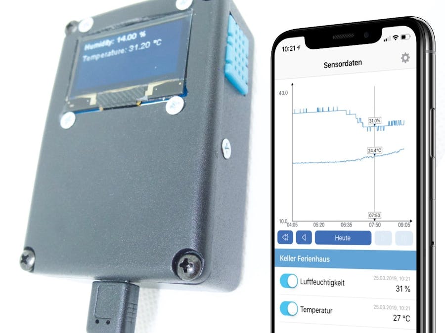
For this project you should be able to use of a saw, file, drill and soldering iron. The result of this project is a compact unit with an integrated sensor and a display for displaying temperature and humidity data of the DHT11 Sensor.
The unit is powered via a Micro-USB connector and can then be configured and used with the Sensate Monitor App.
The solution is based on the software/backend and mobile Applications by Sensate.
Prepare board (cut to size)The first step is to cut the board to the right size. In addition, light recesses are filed into the corners using the round file, so that the board fits well into the desired housing. The less play the board has, the better.
If you are using a board with prepared tracks as shown, make sure that the tracks run as shown (crosswise to the long side).
If it is a board with prepared tracks, the lower 17 tracks have to be cut in the middle.
Use a cutter knife and cut along a row of holes several times with medium pressure until the tracks are cleanly cut.
In this step, the socket strips for the microcontroller as well as a so-called “pull-up resistor” and two supply lines are soldered onto the board. The components are all placed individually on the side without traces and soldered as shown.
If there are no 15-pin socket strips, smaller ones (e.g. 3x5Pin or 1x10Pin+1x5Pin, as shown in the photos) can also be combined. Even longer socket strips are no problem, as long as you pay attention to the position of the microcontroller later on.
Now the microcontroller can be placed on the skirting boards for testing purposes. If you want to work on the board again later, it should be removed again.
If no 4-pin cable is available, you can use a small circuit board and a 1×4-pin socket strip. To do this, solder the socket strip and 4 cables (each approx. 15cm long) as shown on a small (4*3 hole) PCB.
Please pay attention to the orientation of the board, so that one pin of the socket strip is connected with one cable.
Since the sensor used does not have a direct mounting option, the sensor board also functions as a mounting plate for the sensor in this case.
The adapter board is prepared slightly wider so that there is enough space for a mounting hole away from the required tracks. The area in which the mounting hole is drilled should be electrically separated from the remaining area with the cutter knife so that no short circuit can occur.
The sensor is soldered as far away from the PCB as possible so that it can be bent outwards later. The connecting cables (each approx. 15cm long) are soldered directly to the copper side, contrary to the usual procedure, so that the circuit board can later function well as a mounting aid.
Now the connecting cables of display and sensor are connected to the bridge as shown. Since both the supply line (red) and the ground line (blue) run across the entire width of the board, the exact position of the cables is not relevant as long as the row is correct.
The data cables (2 for the display, 1 for the sensor) are soldered next to the pin header of the microcontroller.
In order to draw the outline of the display as well as possible, it makes sense to work with the display as a template. A larger rectangular opening must be made for the display itself as well as 4 mounting holes.
Display openingThe rectangular display opening is best marked from the inside. When opening the display, make sure that the glass of commercially available OLED displays breaks very easily at the edge, i.e. the opening should be large enough for the display. If you later try to push the display into an opening that is too small, there is a high probability that the display will break.
Mounting holesIn addition to the display opening, 4 holes (3mm) are required for the mounting screws. To do this, place the display upside down on the intended position and mark the centre points of the holes (also from the inside).
Cut out the opening for the displayThe mounting holes for the display are simply drilled with a small metal drill (about 3mm). Please make sure that the drill is smaller than the screw head.
For the rectangular recess of the display, first drill a slightly larger hole (e.g. 8mm) within the display area. Be careful not to drill too close to the marked outer edge, otherwise you can see the hole there. Now you can work out the rectangular opening e.g. with a fretsaw (see picture #4). The saw blade of the saw is unhooked on one side, threaded through the hole and then clamped again. Now the opening can be worked out.
Then the edges and corners are embellished with a file or – if necessary – slightly enlarged.
Now that all necessary openings have been made in the upper part of the housing, the display can be mounted. As already mentioned before, the display glass of commercially available OLED screens is very sensitive to lateral loads, so you might need to rework the opening again if it doesn’t go out completely. And: Never press the display into the opening!
If the display is in the opening, it is fastened with 4 screws and the matching nuts. The nuts are held with the fingers, while the screws are fixed with a small screwdriver.
The sensor should be placed in the corner next to the bridge. First draw the sensor as shown.
Now carefully work out the opening for the sensor. Make sure that the opening is not too large to give the sensor some stability through the housing.
If the sensor has been placed for testing, the mounting hole can be marked and drilled with a 3mm drill.
So that the bridge can later be supplied with power from the outside, an opening for the USB socket must now be created. The position of the opening is first marked and then worked out with a file.
Now that the mechanical work on the housing has been completed, the sensor can be mounted. It is fixed with a 2.5mm screw and a suitable nut.
If it is a countersunk screw, the drill hole can still be countersunk slightly with the help of a larger drill (by hand!). Be careful not to drill through!
After the sensor, the bridge can now be installed in the housing.
If the board does not sit stable in the case by itself, it can be fixed in the case with a narrow strip of double-sided adhesive tape.
Closing the case – especially stowing the display and sensor cables – requires a little patience and sensitivity.
Depending on the length of the cables used, it can be a bit difficult to store all cables in the case. Tip: There is usually enough space between the microcontroller and the PCB (i.e. in the free space created by the sockets) to store one or two cables.
If your microcontroller (bridge) has not yet been loaded with the Sensate firmware, follow these instructions. Once this is done, the unit is fully functional and can now be used with the Sensate Monitor App (available for iOS and Android, the links can be found in the component list). Have fun!
You can easily configure the Sensate Monitor App using our Quick-Config-QR-Code. When asked to select an app configuration, select "Scan QR Code", and use the following code:


Comments