


Hardware components | ||||||
 |
| × | 1 | |||
| × | 1 | ||||
_ztBMuBhMHo.jpg?auto=compress%2Cformat&w=48&h=48&fit=fill&bg=ffffff) |
| × | 1 | |||
| × | 1 | ||||
Software apps and online services | ||||||
 |
| |||||
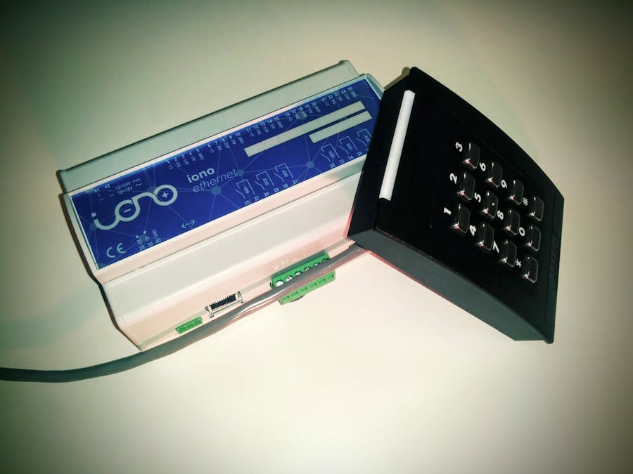
Have a secret room to keep safe? This project shows you how to use a general Wiegand keypad to control an electronic door lock with the help of Iono, an I/O module based on Arduino.
Equipment- Wiegand keypad. I'm using an HID keypad with a beeper and a LED light integrated; I use them to signal an access being granted or denied. You may use any Wiegand keypad and external light and buzzer or just skip them.
- Iono board (both UNO and Ethernet versions are OK).
- Electronic door lock.
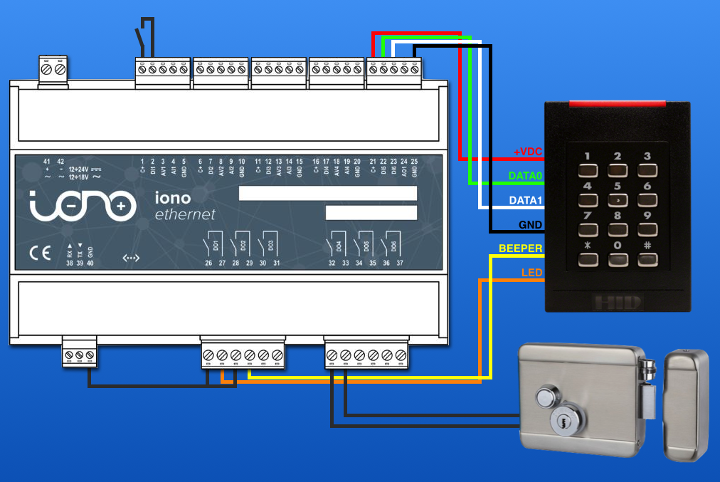
Wire up your components as shown here:
On the Iono board, make sure to move the two DI5 and DI6 jumpers in the bypass position:
After uploading the provided sketch on the Iono board, you are ready to use your access control system.
First, set your pin code: when you set DI1 high (i.e. connect it to C+) the controller goes to programming mode. Enter your secret PIN code on the keyboard followed by '#', the beeper will be activated for 2 seconds. Now your code is stored on Arduino's EEPROM, therefore it will be kept memorized even if you power off the board.
Disconnect DI1 from C+ and you are ready to unlock your door entering your secret PIN (followed by '#').
The provided sketch will alert with 3 short beeps when a wrong code is entered or, in case of correct PIN, will activate the door relay (unlock the door) and the LED relay for 4 seconds and play a 1-second beep.
You can easily modify those behaviours editing the provided sketch to make it fit your needs.
Enjoy it!
Sketch code detailsThis sketch makes Iono a controller for an electronic door lock and a Wiegand keypad.
It reads the digits sent by the keypad using the Wiegand protocol, matches them with the saved PIN code and unlocks the door if correct.
It also signals whether the access has been granted or denied activating a relay for a beeper and an LED (or whatever you attach to Iono's relays).
Finally it provides for a procedure to modify the saved PIN without reprogramming Iono.
The sketch will decode the Wiegand data sent from a keypad that uses 4 bits for a single digit.
The used keypad, other than the digits 0-9, should have a key to be used as terminator.
In this case the key '#' is used, which is sent from the keypad as number 11.
The Wiegand interface has two data lines, DATA0 and DATA1. These lines are normall held high. When a 0 is sent, DATA0 drops to 0V for a few microsec. When a 1 is sent, DATA1 drops to 0V for a few microsec. There is usually a few millisec delay between the pulses.
Your keypad should have at least 4 connections (some have more). Connect the red wire to C+ the black wire to GND, the green wire (DATA0) to DI5 and the white wire (DATA1) to DI6.
Then you should connect your door lock to the realy set as the DOOR_RELAY constant. This relay will be closed when the correct PIN is entered and then open again after OPEN_TIME milliseconds.
Optionally you can use LED_RELAY and BEEP_RELAY to signal the access being denied or granted.
This sketch activates the LED while the door is unlocked and plays 1 beep when unlocking the door and 3 beeps when a wrong PIN is entered.
To set the correct PIN connect the digital input set as the PROGRAMMING_INPUT constant to C+ and enter the new PIN code on the keypad terminated by #. After saving the new PIN the beeper will be activated for 2 seconds after which you should disconnect the PROGRAMMING_INPUT.
The PIN is saved in Arduino's EEPROM, therefore it will be restored even after a power off.


Comments
Please log in or sign up to comment.