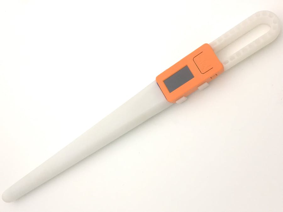
This is another project made with a M5StickC + 3D-printed case. In this build, we will have a deep exploration of the motion sensor in the M5StickC, SH200Q.
For those people who are not familiar with M5StickC, I'd like to list the hardware resources, so that you can have a basic knowledge of this main controller of this project. For more details, please visit: https://docs.m5stack.com/#/en/core/m5stickc
We will use the 6-axis IMU SH200Q apply to a magic wand type of project.
Hardware Resources of M5StickC:
- 5V DC power supply
- USB Type-C
- ESP32-based
- 4 MByte Flash
- 6-Axis IMU SH200Q
- Red LED, IR transmitter, microphone
- 2 Buttons, LCD(0.96 inch), 1 Reset
- 2.4G Antenna: Proant 440
- 80 mAh LiPo battery
- Extendable socket
- Grove port
1. Knowledge of SH200Q
2. How to identify X, Y, Z axis
3. IMU filter algorithm
4. IMU data Capture and Analysis
5. LED display
6. Summary
1. Knowledge of SH200Q1-1 General Description
The SH200Q is a very small, 6 axis inertial sensor, consisting of A digital, triaxial 16bit acceleration sensor and a digital, triaxial 16bit, ±2000°/s gyroscope.
SH200Q delivers an output signal proportional to the angular rate(°/s ), and acceleration(g). We use I2C to get those data.
1-2 Settings
Gyroscope range: ±2000 °/s
Acceleration range: ±8 g
1-3 Raw Data Test
Now Let's keep the device stay still and read out the signal array (X, Y, Z) of both sensors. 10 times gain on Accelerometer:
AX: Acceleration on X-axis GX: Angular acceleration on X-axis
From the data, we can find out 2 things.
1) In this circumstance, C doesn't take other force except for the gravity (1g = 9.8 m/s^2). So the value of Acceleration = SQRT(AX^2 + AY^2+AZ^2) which is around 11g.
2) Theoretically, GX, GY, GZ should stay 0 or very close to 0, but apparently, drift exist in SH200Q. we will have to so some calibration in the code later.
2. How to Identify X, Y, Z AxisWhen we programming a 6-axis sensor to get relatively precise motion info, one common solution is combining accelerometer and gyroscope data.
2-1 The first step is to align their coordinate system, the easiest way to do is to choose the coordinate system of accelerometer as our reference coordinate system.
2-2 By observing the output data from the accelerometer via manipulating the StickC different pose, we can identify the coordinate system of the accelerometer.
1) X-axis
2) Y-axis
3) Z-axis
2-3 Result:
As we mentioned in the last chapter, to get a relatively precise result, we will need a combination of accelerometer and gyroscope data to realize the functionality of the IMU filter. Instead of choosing the complex Kalman filter I prefer this simple and digital operation way - The Complementary Filter-Which is simply obtaining the angular position of the object (on 3-axis: X, Y, Z).
For more details please refer to https://www.pieter-jan.com/node/11
4. IMU Data Capture and Analysis4-1 Magic Wand Requirement
I wish I could detect 3 motions:
1) Point: downward direction
2) Salute: Wrist inward(right hand)
3) Spin: Spin the stick
4-2 Solution
1) Point: as shown in the pic, detecting an increased angle of Y will capture the motion.
2) Salute: Similar to above, detecting a decreased angle of X will capture the motion.
3) Spin: Detecting continues reversing on angular of X and Y.
5. LED displayPorted Arduino library 'FastLED' for Led display. and 'TaskScheduler' for task management.
For the hardware part, we made a led PCB board that carries 92 RGB LEDs and put it inside the stick.
This project, utilizing the basic level of math, but some details and implement methods have not been break down in this article. Please refer to the annotation in code.
The source code is not completely finished yet, but it is complete enough to present the whole framework. Left work would be just function encapsulation and parameter adjusting.
At least, please feel free to contact me if you have any questions about this project.


Comments
Please log in or sign up to comment.