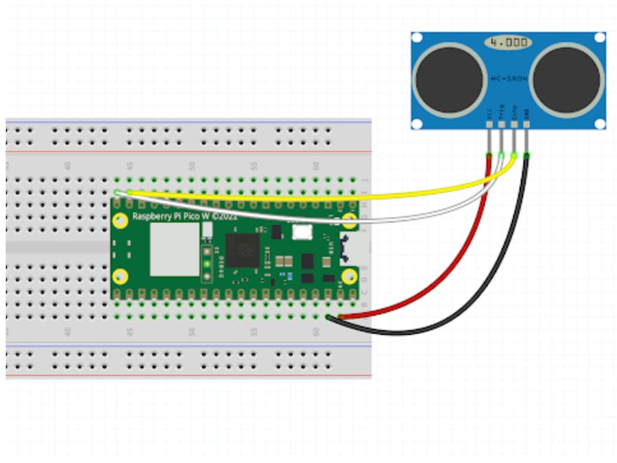
In this tutorial, I quickly demonstrate how to set up the HC-SR04 distance sensor for distance measuring with the Raspberry Pi Pico. I am demonstrating this because it took me a while to find some code that works with 5V logic on the sensor.
Before you begin note that the HCSR04 ultrasonic sensor operates at 5V, which is higher than the voltage tolerance of the Raspberry Pi Pico's GPIO pins (3.3V). Connecting the sensor directly to the Pico's GPIO pins can result in damage to the device. To use the HCSR04 with the Pico, a voltage level converter is required to safely convert the sensor's 5V output to a level that is compatible with the Pico's GPIO pins.
I demonstrate in this tutorial for simplicity, without the additional apparatus but the connections and the code work the same way. However please take precautions from having this setup long-term if you only have one Pico laying around.
-----
Before we get into it, consider subscribing or supporting the channel. Also, be sure to checkout our various stores to shop products for Raspberry Pi, Arduino, ESP32, and DIY electronics at ShillehTek!
Subscribe:
Support:
https://www.buymeacoffee.com/mmshilleh
Hire me at UpWork to build your IoT projects:
https://www.upwork.com/freelancers/~017060e77e9d8a1157
Visit ShillehTek Store for Arduino and Raspberry Pi Sensors and Pre-Soldered Components:
ShillehTek Website (Exclusive Discounts):
https://shillehtek.com/collections/all
ShillehTek Amazon Store:
ShillehTek Amazon Store - Canada
ShillehTek Amazon Store - Japan
1-) Physical Setup:- Get four jumper wires and connect them as shown.
- Note you do not necessarily need a breadboard but I highly recommend it as it will make your life a lot easier dealing with electronics in testing.
- The main point here is that an Echo and a Trig pin is corresponding to the Transmitter and the Receiver respectively. We use the GP14 and GP15 pins on the Raspberry Pi Pico to do this; these are two of many General Purpose Input/Output (GPIO) pins found on the device. These pins can be used for a variety of purposes, such as reading digital signals, controlling LEDs, or communicating with other devices.
- The other two pins (black and red), are used for power (VSYS) and ground (GND). A ground pin (or GND pin) is a pin on an electronic device that is connected to the ground, or zero volts, of the electrical system. Ground pins serve as a reference point for all other voltages in the circuit, and are used to complete circuits and provide a path for electrical current to flow.
- Copy the code snippet from the bottom of this link.
from machine import Pin, time_pulse_us
import time

SOUND_SPEED=340 # Vitesse du son dans l'air
TRIG_PULSE_DURATION_US=10

trig_pin = Pin(15, Pin.OUT) # Broche GP15 de la Pico
echo_pin = Pin(14, Pin.IN)  # Broche GP14 de la Pico

while True:
    # Prepare le signal
    trig_pin.value(0)
    time.sleep_us(5)
    # Créer une impulsion de 10 µs
    trig_pin.value(1)
    time.sleep_us(TRIG_PULSE_DURATION_US)
    trig_pin.value(0)

    ultrason_duration = time_pulse_us(echo_pin, 1, 30000) # Renvoie le temps de propagation de l'onde (en µs)
    distance_cm = SOUND_SPEED * ultrason_duration / 20000

    print(f"Distance : {distance_cm} cm")
time.sleep_ms(500)- Want to thank this gentleman (uPesy) for simplifying this code without the need for external libraries. He deserves most of the credit here but it did take me some time to find this, as all of the other libraries did not work with 5V logic.
- At a high level, the code uses a simple formula to get the distance in centimeters using the speed of sound (some unit conversion is being done as well).
If you have the physical setup and your Raspberry Pi turned on. You should be able to run the code snippet in the MicroPython environment and start getting values. It's that simple! If you enjoyed this or want to see more short tutorials like this please follow me on Youtube.


Comments
Please log in or sign up to comment.