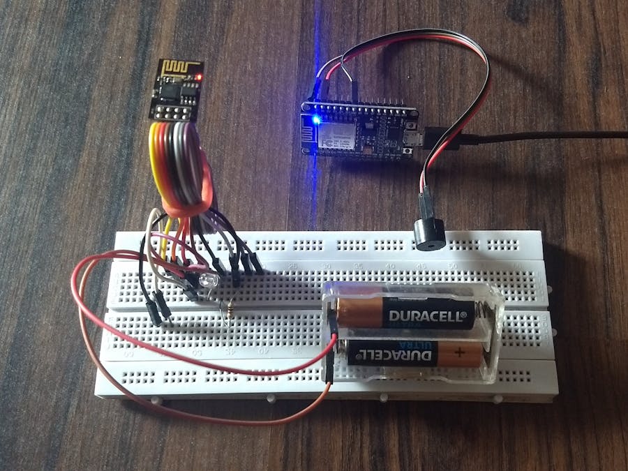
In this project I have used an ESP8266-01 to trigger alerts to the desired destination(buzzer connected to NodeMCU) using the internet via MQTT Protocol. The alert button can be operated from any remote locations provided both the ESP8266's have internet access via WiFi. A single button does the following functions.
1. When the button is pressed for a short duration(between 500 to 1500 milliseconds)- Triggers alert by ringing the buzzer for every short duration (alert-1).
2. When the button is pressed for long duration(more than 1500 milliseconds)-Triggers alert by keeping buzzer high(alert-2).
3. When the button is just clicked(less than 500ms)- Disable alerts.
MQTT ProtocolMQTT is a lightweight messaging protocol that uses publish/subscribe operations to exchange data between clients and the server. I have used this protocol since it is ideal for developing "Internet of things" project as it is faster, uses less data packets and is designed for constrained devices.
The MQTT broker acts as a medium of information exchange between the clients(NodeMCU and ESP8266-01) based on the interested topic.The topic I have used in this project is "alert". Since the ESP8266-01 has to send the status of the pushbutton, it "publishes"data on the topic "alert" to the MQTT broker. On the receiver end, the NodeMCU is "subscribed" to the same topic so it receives the button status. Based on the status of the button received, the buzzer attached to NodeMCU operates. I have used Adafruit io's MQTT broker as it is free and easy to implement. For this, we need to setup the dashboard on the Adafruit io.
Setting up the Adafruit DashboardTo create a new dashboard, I have followed the steps as provided by the adafruit io.
1. After the dashboard is created, you will see a blank screen. To add a block, you need to click on the "+" icon.
2. Select the Gauge block.
3. Create a new feed as "alert" and select the feed. The ESP8266's sketch is programmed to send data to the same feed.
4. Enter the min and max value of the gauge as '1' and '3'. Value '1' is to disable alerts, ' 2 ' is to trigger alert-1 and '3' is to trigger alert-2.
5. The gauge is finally set up and you will be able to see it in your dashboard screen.
To "publish " and "subscribe" the data to/from the gauge, we need to upload the sketch to the NodeMCU and ESP8266-01.
Uploading the sketchThe sketch for both the ESP8266's have been modified from the example sketch(examples-> Adafruit MOTT Library-> mqtt_esp8266 )
If you are new to the ESP8266, make sure to inastall the ESP8266 board on the Arduino IDE. I have followed the steps given here before uploading my first sketch on it.
The sketch requires the following libraries which you can install from the Arduino IDE(tools->Library Manager) itself.
1. Adafruit IO Arduino (by Adafruit)
2. Adafruit MQTT Library (by Adafruit)
3. ArduinoHttpClient (by arduino)
Before uploading the sketch to both the ESP8266 modules, make sure to enter the SSID, Password, Username, Aio key to the sketch.
A separate SSID and Password can also be assigned to both the ESP8266's as they operate via the internet.
The username and aio key can be obtained from the top right corner of the adafruit dashboard. Copy the same in the IDE sketch.
Uploading the sketch to the ESP8266-01 could be a little tricky. I have used the Arduino UNO to program the ESP8266-01. Make the connections as given below.
Select the board in the IDE as "Generic ESP8266 module" and upload the sketch.
If the sketch fails to upload, then re-plug either the 3.3V or ground and try to upload the sketch again. I would suggest the following tutorial given here if the problem persists.
For the NodeMCU, the sketch is comparatively easy to upload. Just select the board as "NodeMCU 1.0(ESP-12E Module)" with the correct COM port and upload the NodeMCU sketch.
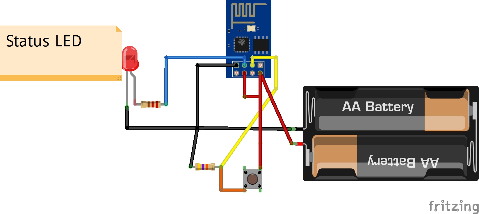
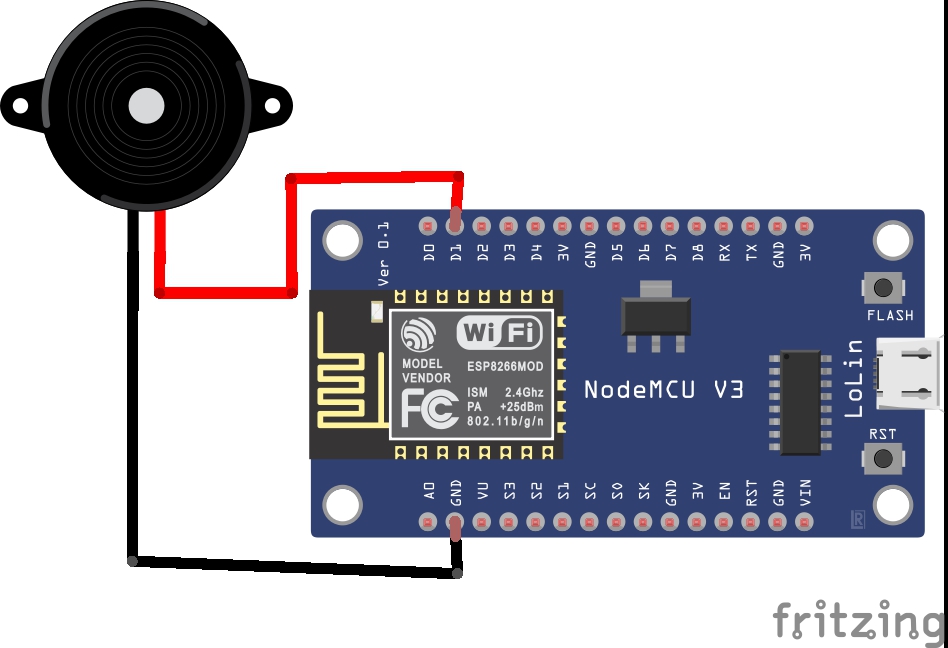
Final ExecutionAfter the Following sketch has been uploaded on both the ESP8266 Modules, make the circuit connections as given in the schematics.
You can use the 3.3V of the arduino to power up the ESP8266-01.I have used a separate 3V supply from 2 AA battery for the ESP8266-01 as it makes the circuit portable, but the battery drained out fast so in the video I have used a partially charged 3.7V li-ion battery(not recommended). I would suggest you to use voltage regulator while using the Li-po/Li-ion batteries (check here for more info).
The led connected to the Pin-2 of ESP8266-01 provides status regarding button press and connection to the MQTT. Initially the LED will blink for one second to denote the connection to the MQTT is successful. If the button is pressed to trigger alert-1(less than 500 and 1500 milliseconds), then the LED blinks at once and if the button is pressed for alert-2(greater than 1.5 sec), then the LED glows until it is turned off(when button is just clicked).
You will notice that the gauge value on the dashboard changes upon pressing the button on the ESP8266-01, it means that the communication on the transmitter side is successful.
If the gauge value changes, then the NodeMCU receives it and rings the buzzer corresponding to the button pressed.The built-in LED of the NodeMCU also provides an indication regarding the connection to the MQTT broker. Initially when the NodeMCU is turned on, the led becomes HIGH indicating it is connecting and when the LED turns LOW, it indicates the connection to the broker is successful.


_ztBMuBhMHo.jpg?auto=compress%2Cformat&w=48&h=48&fit=fill&bg=ffffff)


Comments
Please log in or sign up to comment.