Between the several types of Arduino and other Microcontrollers, we have a problem: the low capacity of electrical current sourcing of the pins.
Where this value can vary between 6 mA to 40 mA in some models. But be careful, always check the datasheet of your device and check the electrical current sourcing capacity of the pins.
But now, to solve this problem, we will use an electrical current driver circuit and we will present all step by step to you construct your own circuit of simple way.
Project DevelopmentThrough the presented problem, the circuit allows you to drive a load whose electrical current is higher than the pin of the Microcontroller can provide. And for that, we will use a transistor.
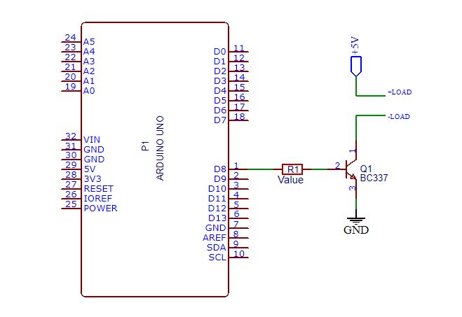
The transistor will be used as a switch and will allow greater electrical current capacity for the load. And for this, we will use this circuit, which is presented in Figure 2, connected to the Arduino pin or any other CHIP. This circuit can be replicated to all digital pins.
As is possible analysis, in this the circuit we use a transistor connected at the Arduino pin through a resistor (R1).
Now, will be presented the process to design all circuit through three steps:
First, we must calculate the base current, which is 10% of the load current value.
This electric current will be supplied by the Arduino pin. For this, we will consider that the load requires 100 mA, our value of Ib (electrical current to activate the transistor base) will be 10 mA.
For each type of load, you need to know what is the electrical current value to drive the load.
Now, note that with a low electric current at the base of the Transistor, we trigger a load that requires a current value 10 times higher.
Therefore, with the value of the base current, we go to the second step: Calculate the resistance of the base with this equation.
Rb = (VDD - 0.7)/Ib - Equation (1)Substituting 10 mA into Ib, we find the resistor value of 430R, which is commercial value.
In the third step, we will dimension the transistor. For this solution, we use NPN transistor BC337 because it supports a collector electrical current of 800 mA, which is larger than the load current.
And the load will be connected in the terminal +load and -load, as is shown in Figure 1.
Therefore, through this project, itis possible to increase the electrical current sourcing capacity of Arduino pins and create projects with loads fo more power.
Our Last Published ArticleLearn how to create the MyPet Maker Board and earn 10 free Printed Circuit Boards. Access this link!
Thanks to the PCBWay for support the our YouTube Channel and produce and assembly PCBs with better quality.
The Silícios Lab thanks UTSOURCE to offer the electronic components.


Comments
Please log in or sign up to comment.