


Hardware components | ||||||
 |
| × | 1 | |||
 |
| × | 1 | |||
 |
| × | 1 | |||
 |
| × | 1 | |||
Software apps and online services | ||||||
 |
| |||||
Hand tools and fabrication machines | ||||||
| ||||||
In several places, we must monitor the security of spaces and prevent intruders from entering prohibited places with the aim of carrying out robberies and thefts. This is very common in businesses and homes and generates great losses.
One way to prevent this problem is through a surveillance and intruder alert system, which is capable of monitoring and warning those responsible when an invasion occurs in their spaces.
Based on this principle we developed an intruder alert system. This system, in addition to monitoring, warns in real time that someone is invading the space. This increases security efficiency and allows those responsible to make decisions to call the police and prevent any problems from occurring.
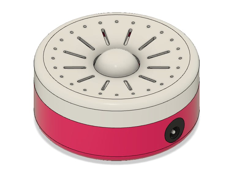
Below we have the developed device.
The device uses a sensor to detect the presence of intruders and sends an SMS with an alert message to a cell phone.
This project was developed in partnership with PCBWay. You can use printed circuit board fabrication and earn 10 free PCB's and use the digital prototyping services to create any product.
Go to this link and download the 3D enclosure to use in your projects.
Next, we will explain the project construction step by step and the programming logic.
Development of the SMS Alert SystemThe developed system aims to, in real time, send an alert to a cell phone and allow an action to be carried out quickly. This speeds up and allows you to call the police to avoid any risk of robbery or break-in.
The project uses three devices:
- Arduino Nano
- Sensor PIR
- Módulo SIM800L
The devices were installed in a case to be mounted on the wall.
What is the working principle of this device?
The Arduino reads the PIR sensor and checks whether or not the presence of intruders is being detected. If the sensor detects movement of people, an SMS alert will be sent through the SIM800L module. This message will be received by the business or home owner.
The SIM800L module is shown in the figure below.
This module uses GSM technology and is capable of sending/receiving calls and SMS messages to any cell phone. During communication you need to insert a GSM CHIP so that it is able to exchange information with the cell phone registered in the Arduino program.
All devices will be installed in the internal structure of the case.
The 3D Structure of the Intrusion Detection SystemThe 3D structure is shown in the figure below. Go to this link and download the 3D file from the enclosure.
The enclosure design will be developed with the Ender 3 S1 Printer in PLA material.
This is the new model developed by Creality. It is capable of printing different materials and has great print quality, accuracy and motion stability during printing.
See other features of the new Ender 3 S1 Printer.
The enclosure is divided into 2 parts: the cover and the box. Below we have the image of the two parts.
The box region has space to store an Arduino Nano and the SIM800L Module. In addition, a hole was inserted in the frame for a power supply connector for the entire device.
The lid structure has threads for easy fixing with the case body. Below we have the structure of the cover. It has a hole for outputting the sensing region of the PIR sensor. You can download now the 3D Enclosure files.
The PIR sensor is installed through screws on the cover structure itself. See the figure below.
To facilitate the fixation of the sensor, use metallic insert nuts in the structure of the holes of the cover.
Below we have the insertion nut.
The nut must be inserted into the holes with the aid of heat. Generally, a soldering iron is used to heat the metallic region of the nuts and facilitate their connection with the holes in the cover. See the figure below.
Next, we will see the structure of the project's programming logic.
System Programming Logic and Control CircuitThe design circuit is shown in the figure below.
The following is the project's programming logic. We will discuss in detail how the code works.
#include <SoftwareSerial.h>

SoftwareSerial chip(10, 11);

String SeuNumero = "+xxxxxxxxxxxxx"; //

#define sensor 12

bool ValorAtual = 0, ValorAnterior = 0;

void setup()
{
  Serial.begin(9600);
  Serial.println("Inicializando Sistema...");
  delay(5000);
  chip.begin(9600);
  delay(1000);

  pinMode(sensor, INPUT); //Configura o Pino do Sensor como Entrada

  ValorAnterior = analogRead(sensor); //Captura um primeiro valor de referencia inicial para a variavel ValorAnterior
}

void loop()
{
  //Le o valor do pino do sensor
  ValorAtual = digitalRead(sensor);

  if(ValorAtual == 1 && ValorAnterior == 0)
  {
      NotIntruder();
      ValorAnterior == 1;
  }

  if(ValorAtual == 1 && ValorAnterior == 0)
  {
      DetectIntruder();
      ValorAnterior == 0;
  }

}

void DetectIntruder() //Funcao para enviar mensagem de alerta Umidade Baixa
{
  chip.println("AT+CMGF=1");
  delay(1000);
  chip.println("AT+CMGS=\"" + SeuNumero + "\"\r");
  delay(1000);
  String SMS = "Intruder Detected";
  chip.println(SMS);
  delay(100);
  chip.println((char)26);
  delay(1000);
}

void NotIntruder()//Funcao para enviar mensagem de alerta Umidade Normal
{
  chip.println("AT+CMGF=1");
  delay(1000);
  chip.println("AT+CMGS=\"" + SeuNumero + "\"\r");
  delay(1000);
  String SMS = "Without Intruder";
  chip.println(SMS);
  delay(100);
  chip.println((char)26);
  delay(1000);
}
For this project, we use library SoftwareSerial. The library will be used to communicate the Arduino with SIM800L Module through serial communication.
#include <SoftwareSerial.h>Next, we'll define what is the pin in the Arduino that will be used like a RX and TX serial communication.
SoftwareSerial chip(10, 11);Subsequently, we need to create a string and add the mobile number to that string. You must enter the + Country Code and your cellphone number after the country code.
String SeuNumero = "+xxxxxxxxxxxxx";After, it was defined as the sensor pin and the variables of the code.
#define sensor 12

bool ValorAtual = 0, ValorAnterior = 0;
Finally, is executed the setup function in the Arduino.
The function void setup() and void loop() in ArduinoIn the serial communication will be initialized the serial of the Arduino pins (digital pin 0 and digital pin 1) and the virtual serial through the library SoftwareSerial with the object chip.
void setup()
{
  Serial.begin(9600);
  Serial.println("Inicializando Sistema...");
  delay(5000);
  chip.begin(9600);
  delay(1000);

  pinMode(sensor, INPUT); //Configura o Pino do Sensor como Entrada
}
Finally, the sensor pin was defined as a digital input pin. Now, in the void loop function, the system will analyze the sensor state and will send the SMS message for the user.
In the code presented below, the system will read the reed switch sensor and will store its value in the variable ValorAtual.
void loop()
{
  //Le o valor do pino do sensor
  ValorAtual = digitalRead(sensor);

  if(ValorAtual == 1 && ValorAnterior == 0)
  {
      ClosedDoor();
      ValorAnterior == 1;
  }

  if(ValorAtual == 0 && ValorAnterior == 1)
  {
      OpenedDoor();
      ValorAnterior == 0;
  }

}
After, the system will verify what was the value read off the sensor. Therefore, was used two conditions to verify the state of the PIR sensor.
In this code presented above, you can see the first condition. It will be presented below.
if(ValorAtual == 1 && ValorAnterior == 0)
  {
      DetectIntruder();
      ValorAnterior == 1;
  }
As is possible to see, case the read value of the sensor is equal at 1 and the variable ValorAnterior is equal at 0, the system will enter the condition.
In this way, the system will execute the function DetectIntruder() and will send the message "Intruder Detected" and hereafter will insert the value 1 for the ValorAnterior variable.
This variable is used to ensure that the code flow enters the condition only once. This prevents the system from sending a message several times, while the door is closed or open.
The other condition has a similar working if compared with the condition presented above.
if(ValorAtual == 0 && ValorAnterior == 1)
  {
      NotIntruder();
      ValorAnterior == 0;
  }
When the sensor has the 0 value returned by the function, the variable ValorAtual will be 0 and the variable ValorAnterior will be 1. In this way, the system will enter in this condition and will execute the functions.
As is possible see, the function NotIntruder will be executed to send the "Withouth Intruder" message for the user.
Finally, the user will receive an alert message and will contact the responsible people or police to verify what is occurring in your sector.
You can download the project and build your own. Access the link now!
AcknowledgmentThanks to the PCBWay for support and produce and assembly PCBs with better quality.
You can use printed circuit board fabrication and earn 10 free PCB's and use the digital prototyping services to create any product.
Access this link and download the 3D enclosure to use in your projects.


Comments
Please log in or sign up to comment.