IntroductionUsing a Radio Frequency receiver circuit is one of the easiest ways to have a one-way communication between two devices. The radio frequency has a corresponding range that ranges from 30 kHz to 300 GHz that exists in the radio frequency communication system. Normally, the digital data can be represented in variations within the amplitude of the carrier wave.
Project ConceptualizationFor this project, 4 LEDs will be controlled using four push-button switches connected to the IC encoder within the radio frequency wireless communication. The radio frequency receiver module collects serial data and supplies it to the decoder IC, which decodes it, thus controlling the 4 LEDs.
Components- AE1 1 Antenna Antenna Connector_Wire:SolderWire-0.1sqmm_1x01_D0.4mm_OD1mm Antenna
- C1 1 0.33uF C_Small Capacitor_SMD:C_0805_2012Metric Unpolarized capacitor, small symbol
- C2 1 0.1uF C_Small Capacitor_SMD:C_0805_2012Metric Unpolarized capacitor, small symbol
- D1, D2, D3, D4, D5 5 LED_Small LED_Small LED_SMD:LED_0805_2012Metric Light emitting diode, small symbol
- J1 1 9V Input Screw_Terminal_01x02 282834-2:TE_282834-2 Generic screw terminal, single row, 01x02, script generated (kicad-library-utils/schlib/autogen/connector/)
- J2 1 RF 433MHz Receiver Screw_Terminal_01x04 282834-4:TE_282834-4 Generic screw terminal, single row, 01x04, script generated (kicad-library-utils/schlib/autogen/connector/)
- R1 1 33k R_Small_US Resistor_SMD:R_0805_2012Metric Resistor, small US symbol
- SW1, SW2, SW3, SW4, SW5, SW6, SW7, SW8 8 SW_SPST SW_SPST Button_Switch_SMD:SW_SPST_PTS645 Single Pole Single Throw (SPST) switch
- U1 1 HT12D HT12D Package_SO:SSOP-20_3.9x8.7mm_P0.635mm 2^12 serial decoder, SOP-20
- U2 1 L7805 L7805 Package_TO_SOT_SMD:ATPAK-2 Positive 1.5A 35V Linear Regulator, Fixed Output 5V, TO-220/TO-263/TO-252
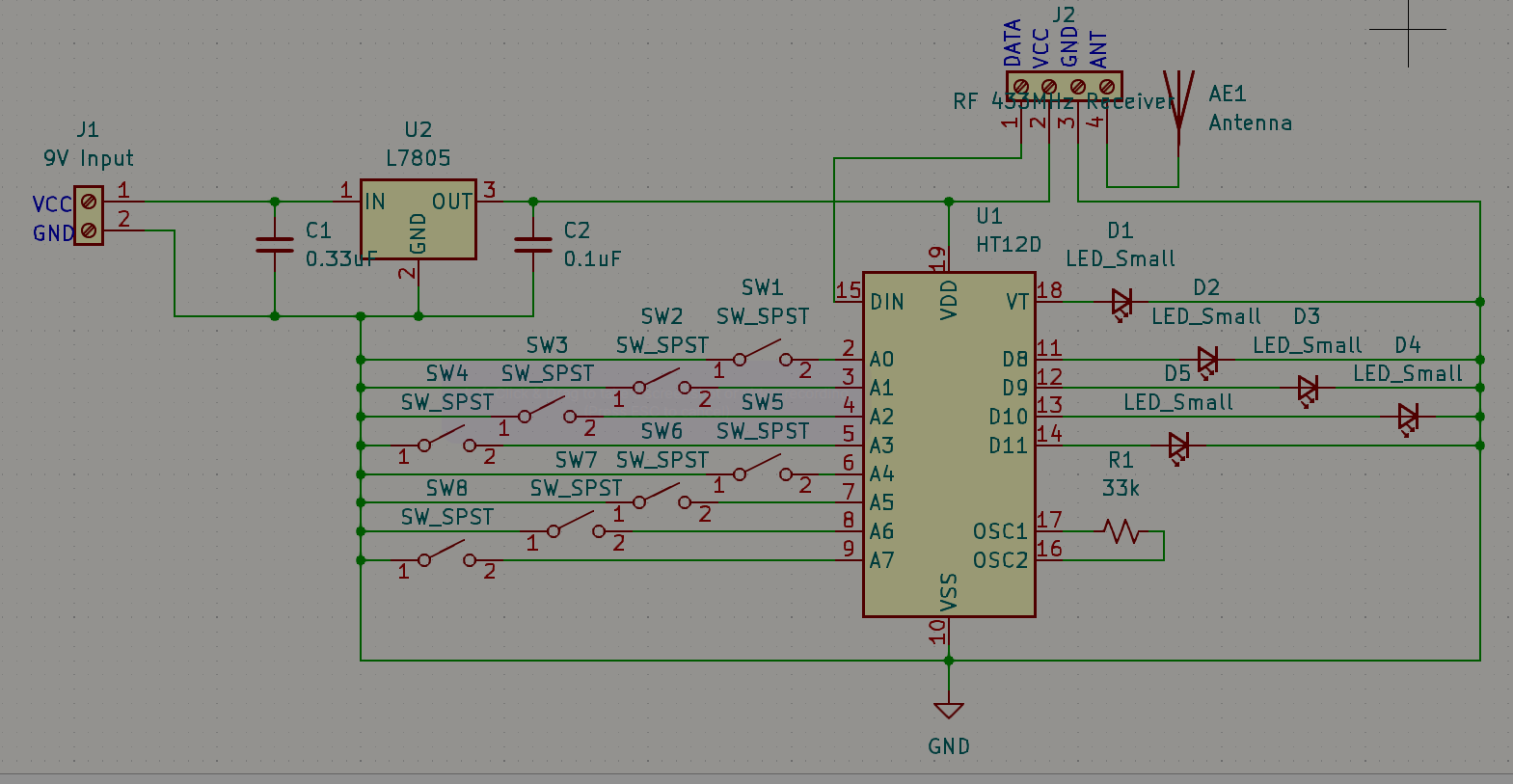
RF Receiver Circuit Diagram
RF Receiver Circuit DescriptionThe VSS pin of the HT12D decoder IC is linked to the negative terminal of the power supply, while the VDD is connected to the positive output (Vout) of the 7805 5V voltage regulator. Pins A0 to A7 (pins 1 to 8) on the IC are grounded to set the address to 0b00000000. LED2, LED3, LED4, and LED5 are individually connected to D11 (pin 13), D10 (pin 12), AD9 (pin 11), and D8 (pin 10). A 33K ohm resistor is positioned between pins 15 and 16 to provide the necessary external resistance for the internal oscillator of the HT12D IC to function. The ground (GND) pins of the RF Receiver module are linked to the negative terminal of the power supply, and the VCC is connected to the positive power supply (VCC+). The Data pin is joined to the DIN (pin 14) of the IC.
How the Radio Frequency Receiver Circuit OperatesOn the recipient's end, the RF receiver module takes in the incoming serial data sent by the transmitter. Subsequently, this serial data is directed to the HT12D Decoder IC's DIN pin (14). The decoder IC then transforms the received serial data into 4-bit parallel data. These four data pins on the decoder IC are linked to four LEDs, and the data transmitted by the transmitter controls them. When power is supplied to both circuits, you will observe that all the LEDs will begin to illuminate. This is because the Encoder IC internally pulls up the push-button pins (specifically IC pins D8-D11). Pressing one of these push buttons will connect the respective data pin to the ground in the transmitter circuit, causing the corresponding LED in the receiver circuit to turn off.
Where and How Do You Order Such Boards?Looking at the PCBWay website, I discovered three important features while ordering your PCB for fabrication and assembly. Through PCBWay, you can order a turkey project where PCBWay supplies the parts, a kit where the customer supplies all the parts or a combo where the customer supplies some of the parts while PCBWay does the rest. This service depends on the customer's preference, thus making PCBWay one of the most flexible fabrication houses I can always recommend to a friend.


_4YUDWziWQ8.png?auto=compress%2Cformat&w=48&h=48&fit=fill&bg=ffffff)

_Ujn5WoVOOu.png?auto=compress%2Cformat&w=40&h=40&fit=fillmax&bg=fff&dpr=2)
_3u05Tpwasz.png?auto=compress%2Cformat&w=40&h=40&fit=fillmax&bg=fff&dpr=2)
Comments
Please log in or sign up to comment.