In this project, our focus is to build a 555 Timer Brushless DC Motor Driver Board which will be based on the 555 Timer IC and the DRV10866 IC. DC Brushless motors are used in computer support peripherals such as disk drives, handheld power tools, printers, automobiles, drones, and aircraft. DC Motors requires relevant information for it to be able to select the best angle and speed to drive the system. This is where the driver circuit comes in to play such a role. In most applications, we incorporate the Hall Effect Sensor but in our advanced system, we will build a board that can replace the sensor and perform well as expected.
Important Components for the Board
Below is a list of the components relevant to build the circuit which later we convert into our board;
· Resistors; 10k, 100k, and 3.8k.
· Variable Resistor; 5k
· Capacitors; 10n two in quantity, 0.1u, 2.2u all should be ceramic disc.
· NE555 Timer
· Schottky diode BAT41; 2 in quantity.
· DRV10866 3-phase BLDC driver IC for motors.
· Connector for 5V power supply.
Brushless DC Motor (BLDC)These are types of synchronous motors that are powered by the direct current through an inverter or preferably a switching power supply system that injects voltage as AC to drive each connected motor phase by adapting the closed-loop controller mode. The controller delivers pulsed current to the windings of the DC motor which ends up controlling the motor’s torque and speed. The such motor has a high power-to-weight ratio, low maintenance, and high speed compared to other motors.
DRV10866 Motor Driver IC
This is a three-phase motor driver. It is sensorless, integrated with MOSFETs, and has a drive current capacity of about 680mA peak. The driver is specifically used in low noise and few external components count motor fan drive application. The driver has a voltage input ranging between 1.65V and 5.5V. it has modern advanced specifications such as UVLO, Voltage surge protection, thermal shutdown, and lock detection.
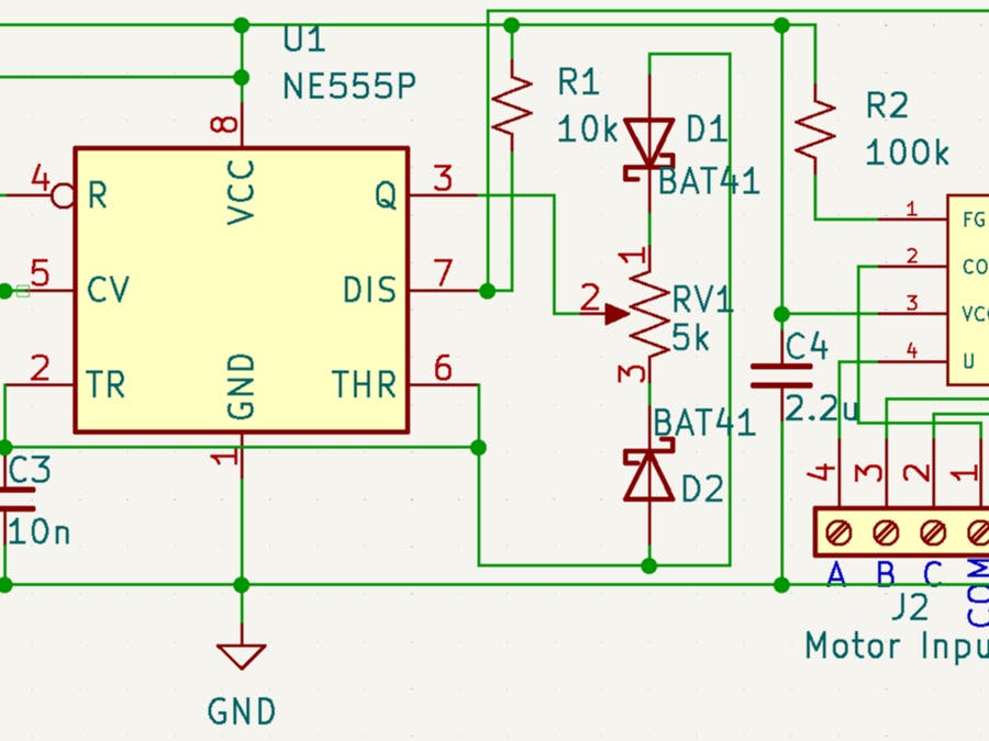
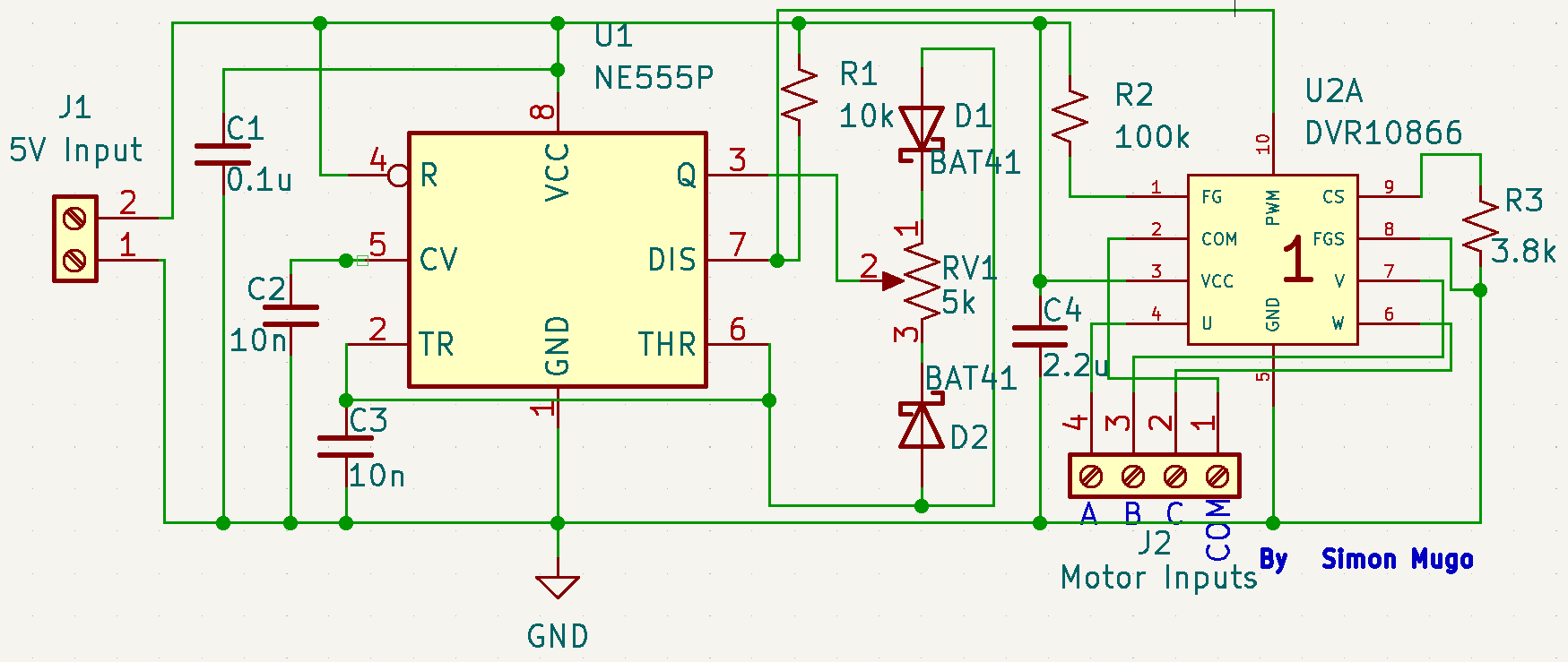
The Circuit DiagramThe circuit diagram for this project is given above. The main components are the 555 IC and DRV1010866.
A pull-up resistor of 100K is connected to DRV10866 Pin 1. Pins 2, 4, 6, and 7 of the DRV10866 are connected to common, phases A, Phase C and Phase B of the motor. The DRV10866 pin 10 is connected to pin 7 of the NE555P timer IC to receive PWM signals used to control the motor speed.
The output signal is at pin 7 of the timer IC. The potentiometer in the circuit is used to adjust the PWM signals by adjusting the duty cycle. The duty cycle can be varied using the potentiometer to a range of 5% to 95% hence controlling the speed of the connected DC motor.
PCB Layout and 3D RenderingBelow is the PCB layout completed using KiCAD EDA.
The figure below is an indication of the 3D output done in the KiCAD EDA tool.
Are you worried about how you can order your printed circuit board manufactured and delivered to your doorstep most cheaply and quickly as possible while ensuring that quality has been achieved? Worry no more. PCBWay, one of the best PCB manufacturing companies has the best offer when it comes to shipment of manufactured PCB boards. You need to Get a Project Quote on PCBA orders and you will receive up to $30 shipment cost reduced for you. Also, you get an assembly service promotion of only 3$0 for in total of 1 to 20 assembly stencils free plus free shipment.


_4YUDWziWQ8.png?auto=compress%2Cformat&w=48&h=48&fit=fill&bg=ffffff)


_Ujn5WoVOOu.png?auto=compress%2Cformat&w=40&h=40&fit=fillmax&bg=fff&dpr=2)

Comments
Please log in or sign up to comment.