IntroductionThe Arduino Customized L298M Dual Motor Driver Module is designed to handle high-power DC and Stepper Motors. It comprises an L298 motor driver IC and a 78M05 5V regulator. The module enables control of up to 4 or 2 DC motors with directional and speed adjustments.
Specifications of a L298MThe various specifications, as well as the features of an L298M motor driver module, include;
- Ø A L298N 22A driver model
- Ø L298N double H bridge driver chip.
- Ø A 46V maximum motor voltage.
- Ø 2A maximum motor current
- Ø 5V logic voltage
- Ø 5-35V driver voltage
- Ø 2A driver's current
- Ø 0 to 36mA logic current
- Ø 25W maximum power
- Ø Current sense for every motor
- Ø Power-on LED indicator
- Ø A heatsink that upgrades the performance
Module’s Pinout ConfigurationThe L298N Motor Driver Module has various pins that serve multiple functions. The IN1 and the IN2 control motor A’s spinning direction, while IN3 and IN4 control motor B’s spinning direction. Both ENA and ENB enable PWM for motors A and B, respectively. The OUT1 and OUT2 pins are the output pins for motor A, whereas OUT3 and OUT4 are the output pins for motor B. The 12V plug is also the input DC, and the 5V pin supplies power to the L298n IC’s switching logic circuitry. Lastly, the GND is the ground pin.
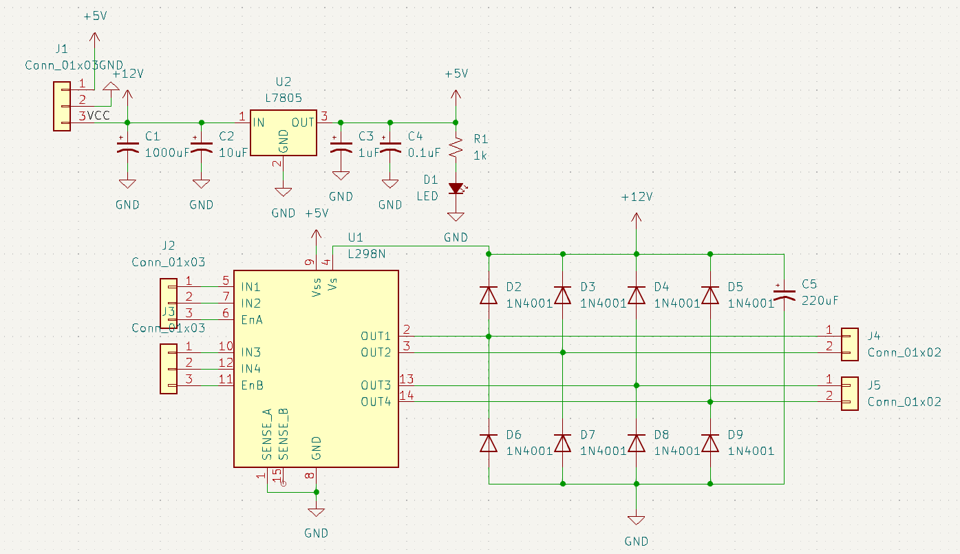
What does L298M entail?The L298N Motor Driver module incorporates an L298 Motor Driver IC, 78M05 Voltage Regulator, resistors, capacitor, Power LED, and a 5V jumper in an integrated circuit. The 78M05 regulator activates when the jumper is in place, powering the internal circuitry when the supply is ≤12V. The 5V pin functions as an output to power the microcontroller. For supply >12V, the jumper is removed, and a separate 5V input is provided to power the internal circuitry. ENA & ENB control Motor A and Motor B speed, while IN1& IN2 and IN3 & IN4 determine their directions.
L298N Motor Driver with the ArduinoNow, let's apply these concepts practically. For our first example, we'll control motor speed with a potentiometer and change rotation direction using a push button. Here's the circuit diagram:
Components needed: L298N motor driver, DC motor, potentiometer, push button, and Arduino board.
Arduino ProgramIn the program, first, define pins and variables. In the setup section, set pin modes and the initial rotation direction of the motor. In the loop section, read the potentiometer value, map it to the PWM signal (0-255), and send it to the L298N board's Enable pin using analogWrite(). Check if the button is pressed; if true, change the motor's rotation direction by setting Input 1 and Input 2 inversely. The push button functions as a toggle, altering the motor's rotation direction each time it's pressed.
Easy Way to Manufacture This ProjectTo all readers, such a project can be manufactured for you through many manufacturing companies around the globe. I have always preferred working with PCBWay due to its benefits. One of the top benefits you get is project sponsorship. PCBWay has sponsored thousands of projects worldwide, especially for educational purposes. To benefit from such projects, you must visit their sponsorship page, follow the easy steps, and apply.


_4YUDWziWQ8.png?auto=compress%2Cformat&w=48&h=48&fit=fill&bg=ffffff)


_Ujn5WoVOOu.png?auto=compress%2Cformat&w=40&h=40&fit=fillmax&bg=fff&dpr=2)


_3u05Tpwasz.png?auto=compress%2Cformat&w=40&h=40&fit=fillmax&bg=fff&dpr=2)
Comments
Please log in or sign up to comment.