Recently, I’ve got to play with a simple IR controlled CARSON Easy Tyrann 200 Boost helicopter model (two main contra-rotating rotors and a rear tilt rotor for flying forward and backward). The model seems to be perfectly optimized for indoor flying, but it lacks a camera with a birds-eye view. Though ESP32-CAM is relatively lite and the helicopter can easily enough fly it in the air, the camera still needs a power supply. Adding a dedicated battery for the camera would make the helicopter overweight for flying, so the only option was to draw the power from the original 3.7 V, 150 mAh Lithium helicopter battery.
However, there were four problems that needed to be solved: how to preserve the helicopter center of gravity, how to make the camera removable, how to provide battery power to ESP32-CAM module which power supply voltage may not exceed 3.6 V and how to lower the helicopter motors electrical noise to an acceptable level to enable ESP32-CAM module operation even at full throttle.
Let’s get to work and find out how to add a power connector for the camera…The helicopter is meant to be repairable, so the cabin is attached to the chassis with 4 screws, 2 from each side. A small maintenance screw driver (mostly for changing damaged rotor blades) is also included with the helicopter. As the cabin is removed the battery power contacts on the helicopter control board are exposed. A pair of ESP32-CAM power supply lines needs to be soldered to the helicopter control board power supply pins in parallel to the battery power supply lines.
I decided to feed the battery voltage to a new homemade power connector that I would had previously glued to the helicopter chassis. I made the connector of 2 two pin PCB receptacles, where the first one (with contacts removed) I had glued directly to the helicopter bottom to achieve the about 2 mm distance, and then I glued the second one with the two contacts on the top of it. See a photo for details. I also clearly marked the polarity of the connector pins.
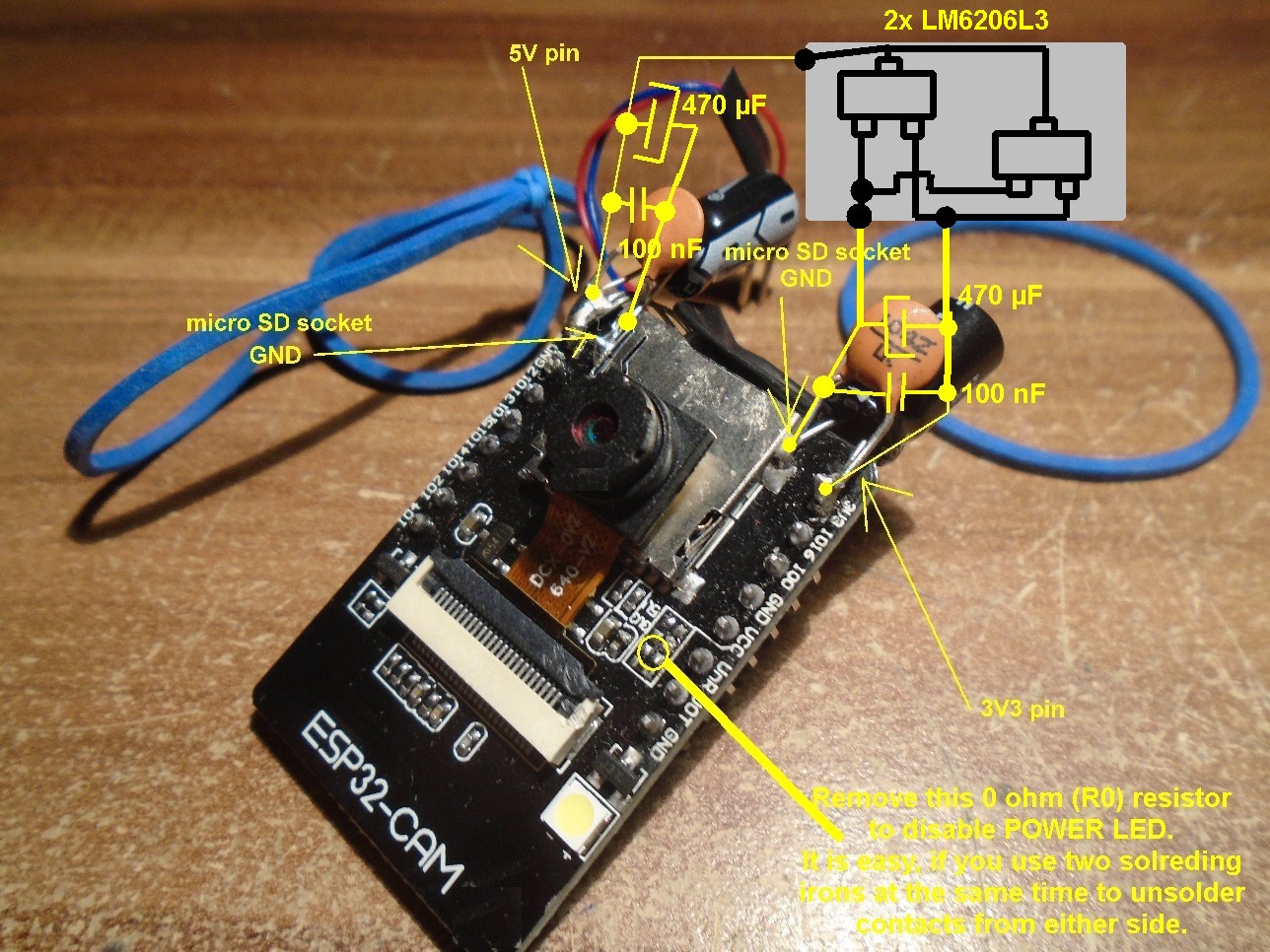
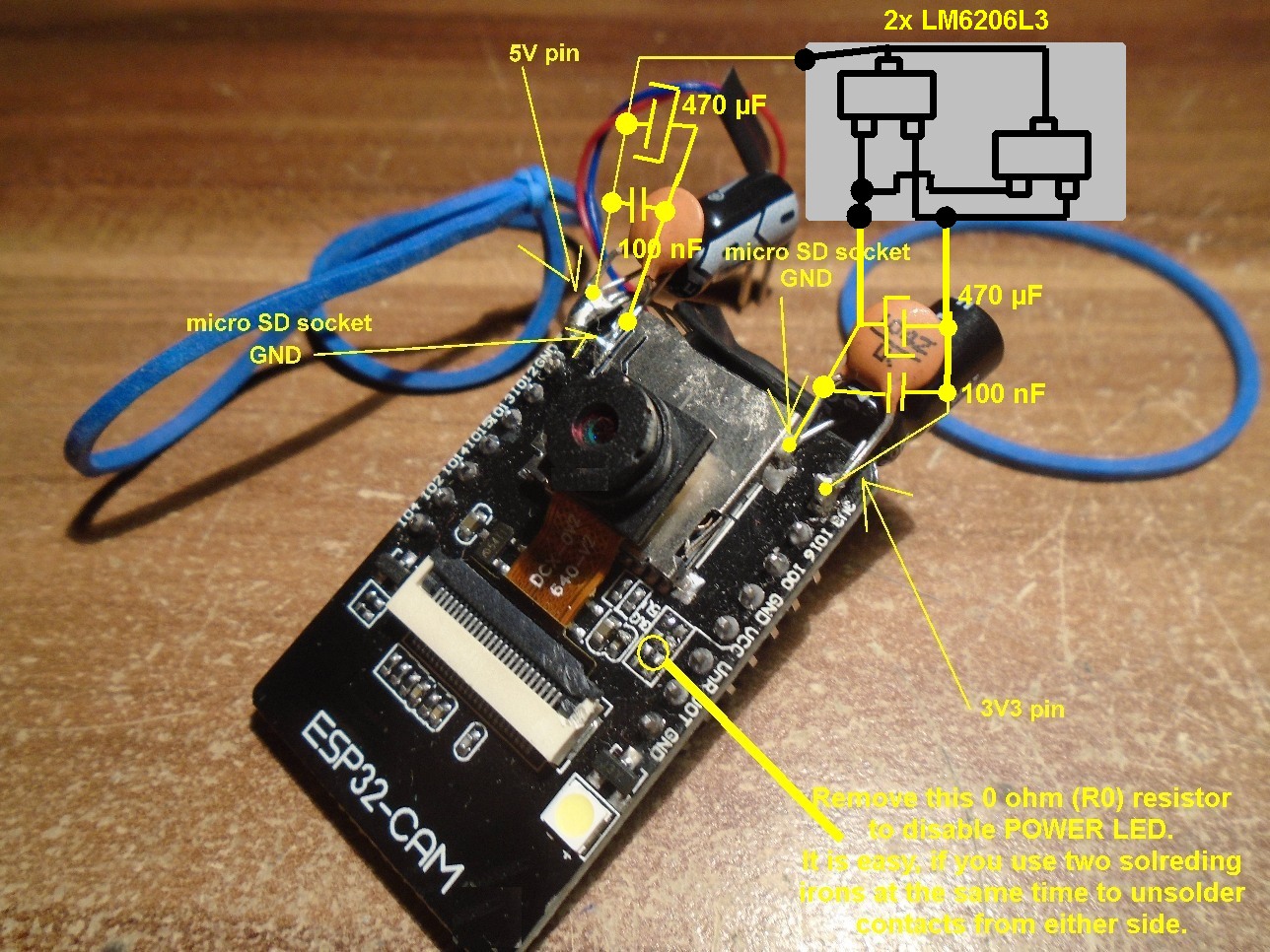
Modifying the ESP32-CAM moduleESP32-CAM module has an inbuilt AMS1117 voltage regulator that lowers the voltage from approximately 5 V to 3.3 V. But the Lithium battery provides between about 3.5 V (when discharged) and 4 V (when fully charged). The AMS1117 starts to work erratically when the battery voltage drops below 3.7 V. To overcame this problem, a low voltage dropout regulator may be used. LM6206L3 voltage regulator may be used in parallel with AMS1117 regulator to provide 3.3 V output voltage when the input voltage is between 3.3 V and 4 V. However, LM6206L3 limits output current to 250 mA, so another LM6206L3 regulator must be used to double the maximum output current to 500 mA. The latter also enables Wi-Fi functionality.
The next step is to add pairs of two 470 µF/10 V and two 100 nF capacitors between “5 V” power supply pin and ground and between “3.3 V” power supply and ground. This assures proper ESP32-CAM module operation even at full throttle when battery is fully charged.
Yet another modification for ESP32-CAM module is necessary enable using micro SD card without flashing the inbuilt power LED. Remove an SMD resistor on ESP32-CAM module to disable flashing the power LED as shown on the photo below.
Materials used and short circuit protectionDespite adding a modified ESP32-CAM module I tried to keep additional weight as low as possible. I used a wrapping wire to feed power a connector that I made from two 2-pin PCB receptacle. The advantages of wrapping wire are: it is very flexible, it has a single metal cord under plastic insulation and it is very lite.
I also used elastic rubber straps to secure the ESP32-CAM module together with OV5640 or OV2640 camera to the helicopter airframe. You must place the straps carefully to prevent overstressing the airframe and to place ESP32-CAM board as high as possible to allow the helicopter to sit on its skids when not flying. There are also other camera module attachment options, especially the ones that enable the camera to face forward. The camera cable is flexible, so only a little support from the back is needed to make face forwards. You can use a sticky tape or an electronics insulation tape (like me) to make the camera face forward.
Programming ESP32-CAM moduleA modified ESP32-CAM module can only be programmed with 3.7 V to 4 V (connect pin 5V and GND) or 3.3 V power supply (connect pins 3.3 V and GND). The helicopter battery may be used as a power supply. Firmware is programmed through TxD0 and RxD0 lines, so any USB to RS232 bridge would do nicely. The only other requirement is to connect a 1 kOhm resistor between GPIO0 and GND pins to tell ESP32-CAM module to boot to programming mode.
You can program the standard AI-Thinker ESP32-CAM firmware that you can download from the internet or use the Tractor project camera module firmware from PC USB Projects download site.
How to fly the helicopter with ESP32-CAM module attached?It is usually difficult to fly the helicopter from a flat ground when ESP32-CAM module is attached, but if you put it on a pillow, OV2640 camera dips in the pillow and the helicopter may still sit on its skids. You need to pull the main rotors speed leaver quickly to takeoff. Alternatively, you may use an Omni Vision camera with a longer connection cable to the ESP32 module (I used 5 meg pixel OV5640), so it can be strapped at the back of the helicopter. But I prefer OV2640 camera with a short cable underneath the helicopter, because it is the easiest to make face forward. However you mount the camera, it is important to get the center of gravity right.
More experienced pilots may also fly the helicopter of hand (like I usually do), but I don’t advice it since you may hurt you face by a rotor blade. The helicopter with the camera attached handles similarly then without it, but the main rotor control leaver responds slower and the flight time is shortened by half, form approximately 8 minutes to about 4 minutes.
At the end, I must stress that you are modifying the helicopter and flying it with ESP32-CAM module exclusively on your own responsibility and that you would almost certainly loose the warranty if you add the power connector as suggested in this article. I nevertheless decided to do it, because it is a great fun to watch inflight videos and it seems not much could go wrong with the helicopter in the future that is covered by the warranty.
READ MORE ON : https://sites.google.com/site/pcusbprojects/5-custom-projects/mounting-a-camera-to-a-drone
WARNING:
You are building this project exclusively on your own risk. You will almost certainly loose the warranty if you do the required modifications. There may also be risk of fire if you accidentally short circuit the inbuilt helicopter battery by accident or in an air crush.


Comments