In many parts of the world wildfires are a serious problem, with huge economic and environmental impacts, including significant danger to human life. Here in Australia we know of these impacts all too well. At the time of this writing, the weekend saw the Australian capital under a State of Emergency, with a 56, 000 Ha bushfire burning out of control.
To date, the Australian bushfires of 2019-2020 have burnt more than 18 million Ha; the Amazon rainforest fires of 2019 burnt an estimated 0.9 million Ha. The Australian fires have destroyed more than 6, 000 buildings, and the economic costs are estimated to exceed 4 billion of dollars. The University of Sydney estimates that over 1 billion animals have died as a consequence of these fires, driving some to extinction.
The toll to human life has so far reached 34 lives lost, including 3 firefighters. At present, two helicopters have crashed, the pilots escaping with only minor injuries. However, only the other week a C-130 tanker crashed whilst water bombing south of the Australian capital, killing all 3 of its American aircrew.
What can we do to help combat these fires? What can we do to reduce to risks to our firefighters?
This project details a Proof of Concept (PoC) that could potentially assist firefighters. It is designed to monitor the escape routes of a fire crew, ensuring a safe retreat whilst they concentrate their efforts on the fires before them.
DesignThe design goal of the Guardian Angel is to utilise all of the components included in the HoverGames competition. It does not try to utilise any other components, so as to focus the learning experience. As a PoC it explores each component and how they can be integrated with each other.
The central component in the design is the PX4 autopilot, which is implemented by the NXP RDDRONE-FMUK66. This central component is the flight controller, responsible for flying and maintaining the hover drone in the air. It itself consists of several sensors.
Attached to the flight controller, via the I2C bus, is the heat sensor (a Melexis MLX90614 IR sensor) and a Pixy2 AI camera. Also attached to the flight controller, on the UART port and communicating bidirectionally via the MAVLink protocol, is an NXP Rapid IoT MCU.
Finally, a Ground Control Station (GCS) is used to monitor and send commands to the flight controller. As the GCS will be on the ground and the flight controller mounted on the hover drone, communication occur over the telemetry radio using the MAVLink protocol.
A key feature to this design is that sensor values aggregates on the flight controller and are sent to the GCS. This design enables firefighters to get instant information about what the hover drone is sensing. Another key feature to this design is the ability for the Rapid IoT component to also access the aggregated sensor values from the flight controller. This feature could enable the implementation of adaptive behaviour.
Although not indicated in the above Logical Architecture diagram, this design allows for easy expansion into the cloud. With connectivity to the Internet, the GCS can send the sensor values it receives from the flight controller up to the cloud as telemetry. A firefighting central command could then view and analyse data from multiple fire crews/hover drones. Predictive algorithms could also be employed.
AssemblyFirst the hover drone needs to be built. To do this follow the instructions provided by NXP: https://nxp.gitbook.io/hovergames/userguide/assembly
My personal implementation varied slightly to the one described in the link above. I desired a neater build, particularly in the mounting of the ESCs. To achieve this, I routed my ESCs and cables slightly differently. I also did not want to use double sided tape and instead relied on cable ties.
The use of cable ties across the ESCs in the orientation I used, required a custom arm bracket to be made. This custom arm bracket allowed for the cable ties fit through a bottom plate hole, which otherwise would have been blocked by the arm mount that came with the kit.
Another aspect to the build that I modified was the mounting of the GPS antenna. Personally, I prefer that when folded down it be at right angles to the front of the drone (i.e. between the front-right and rear-right rotor arms). This orientation required another custom bracket to be made. By using the top plate cut-outs, a mount with a single screw was implemented.
A recommendation in the NXP instructions is to use the shorter GPS rod. This is because both the long and the short rods do not have a tight fit against the cone nut. The long rod will appear to wobble more than the shorter rod, due to its longer length. However, I chose to use the longer rod, giving less electromagnetic interference. To remove the play, I wrapped a loom band around the rod several times, providing a damper for the cone nut.
My final deviation from the NXP instructions was the mounting of the telemetry radio. I did not like the idea of using double sided tap, and a cable tie could not guarantee that it would be securely fastened. Therefore, another bracket was created to hold this radio using the top plate cut-outs, with cable ties now able to hold it securely in place.
A recommendation by NXP was to replace the landing gear T-brackets as the provided ones break easily. One of mine did break, without any hard landings. Therefore, I would recommend not even using the provided T-brackets and just 3D print stronger ones. I also liked the idea of the end caps for the rotor arms. (Both listed in the custom parts.)
In order to hold the NXP heat sensor board and Pixy2 AI camera a custom bracket was made, sliding onto the camera rails at the front of the hover drone. So that two I2C sensors could be utilised on the one I2C external port, available on the flight controller, the Pixy2 had to be soldered directly onto NXP heat sensor board.
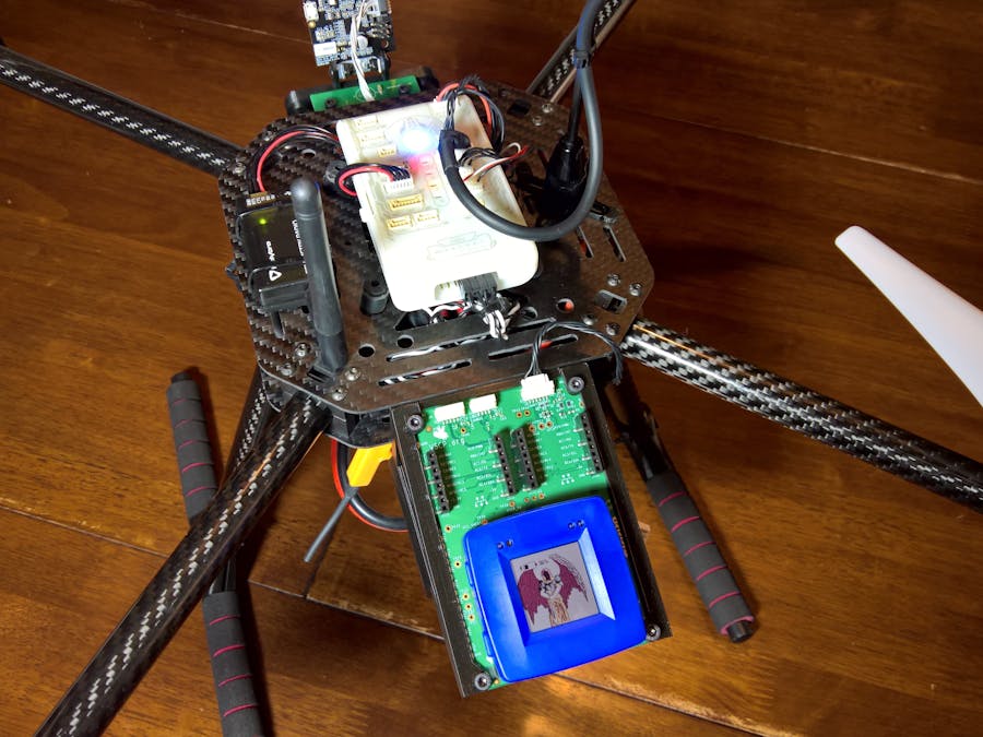
To hold the RDDRONE-IOT board, which in turn holds the NXP Rapid IoT MCU, a final custom bracket was made. This bracket slides onto the camera rails at the back of the hover drone, angled down so that the screen can be view more easily
Toolchain
The toolchain is a significant part of this project. It is recommended that the VirtualBox VM supplied in the NXP instructions be used.
With time permitted, a detailed review of this experience would be documented.
Customisation
The PX4 autopilot firmware was customised, in order to create sensor drivers for each of the sensors and Rapid IoT MCU. As well as this, custom uORB messages were made for each sensor and the MAVLink library was extended to support these messages to the GCS.
The Rapid IoT MCU was customised to display a graphic of a Guardian Angel, by utilising the Atmosphere web interface and custom compiling its output.
ConclusionWildfires are an ancient phenomenon, but with technology we have the potential to mitigate some of its dangers. Technologies such as hover drones are already starting to assist our emergency personnel, including firefighters. Although they may never take the place of water bombing aircraft, they have already shown their value in reconnaissance.
The Guardian Angel is a PoC that explored the opensource PX4 autopilot flight stack using various NXP based sensors. It demonstrated its viability as a platform to support innovative ideas using drone technology. Furthermore, I believe that this platform could be used to assist firefighters and our other emergency personnel.


Comments
Please log in or sign up to comment.