Hackster is hosting Hackster Holidays, Ep. 7: Livestream & Giveaway Drawing. Watch previous episodes or stream live on Friday!Stream Hackster Holidays, Ep. 7 on Friday!
Brijesh Singh
Published © GPL3+

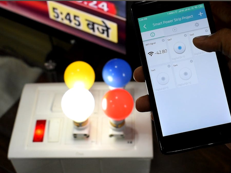
Smart Power Strip v2.0 with Cayenne Cloud

Build your own easy or simple DIY smart power strip to control electrical devices from remotely.

IntermediateWork in progress5 hours1,853
Smart Power Strip v2.0 with Cayenne Cloud

Things used in this project

Hardware components

Smart Power Strip Controller Board (4Channel)
×1
Electrical Switch box
All Electrical Components purchased from the local shop. For better understanding about Electrical components buy check Packaging section
×1
Electrical Socket 3pin
You can also use 2 pin
×4
Live/Phase indicator
×1
Plug wire 2 pin
×1
2Way Electrical Switch
optional, needed only if interested to control device from the physical switch also
×2
Some electrical wires for connection
10-12AWG or around 2mm diameter
×1

Software apps and online services

Arduino IDE
Arduino IDE
Cayenne
myDevices Cayenne

Hand tools and fabrication machines

Multitool, Screwdriver
For connecting wires into screw terminal and electrical switches
Wire Stripper & Cutter, 18-10 AWG / 0.75-4mm² Capacity Wires
For cutting wires during electrical connection

Story

Read more

Schematics

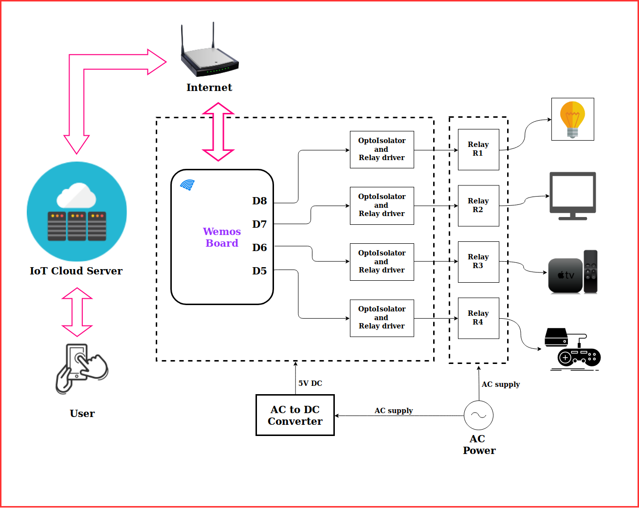
Project Working Block Diagram

Code

SmartPowerStrip_testcode

Arduino
/*
 *              Wemos D1 Mini pin configuration details
 *
 *                     ______________________
 *                    /                      \
 *                   |                        |
 *           (RST) 1 | RST                 TX | 22  (GPIO1)
 *          (ADC0) 2 | A0                  RX | 21  (GPIO3) 
 *        (GPIO16) 4 | D0                  D1 | 20  (GPIO5) <SCL>
 *  <SCk> (GPIO14) 5 | D5                  D2 | 19  (GPIO4) <SDA>
 * <MISO> (GPIO12) 6 | D6                  D3 | 18  (GPIO0)
 * <MOSI> (GPIO13) 7 | D7                  D4 | 17  (GPIO2)
 *  <SS>  (GPIO15)16 | D8                   G | 15    (GND)
 *          (3.3V) 8 | 3V3                 5V | USB    (5v)
 *                    \                       |
 *                    -| Reset  ______  D1mini|
 *                     |_______/\____/\_______|
 *              
 * 
 */

//GPIO pins used to drive relay
const int Relay4 = 14;        //ESP8266 GPIO14 pin D5(on Wemos)
const int Relay3 = 12;        //ESP8266 GPIO12 pin D6(on Wemos)
const int Relay2 = 13;        //ESP8266 GPIO13 pin D7(on Wemos)
const int Relay1 = 15;        //ESP8266 GPIO15 pin D8(on Wemos)

void setup() {
  //configure GPIO pins as output
  pinMode(Relay4, OUTPUT); 
  pinMode(Relay3, OUTPUT); 
  pinMode(Relay2, OUTPUT); 
  pinMode(Relay1, OUTPUT); 

  //Here Active Low Logic used so Relay(SwitchON when GPIO pins are low)
  //so to keep SwitchOFF initially issue HIGH command
  digitalWrite(Relay1, HIGH);
  digitalWrite(Relay2, HIGH);
  digitalWrite(Relay3, HIGH);
  digitalWrite(Relay4, HIGH);

  pinMode(LED_BUILTIN, OUTPUT); // pin mode setup for onboard led
}

void loop() {
  // This code just SwitchON relay for few seconds and 
  // then SwitchOFF, process keeps on repeating
  digitalWrite(LED_BUILTIN, LOW);    // Onboard LED SwitchON 
  digitalWrite(Relay1, LOW);         // Relay1 SwitchON command
  delay(1000);                       // wait for 1 second
  digitalWrite(Relay1, HIGH);        // Relay1 SwitchOFF command
  delay(1000);                       // wait for 1 second
  digitalWrite(Relay2, LOW);         // Relay2 SwitchON command
  delay(1000);                       // wait for 1 second
  digitalWrite(Relay2, HIGH);        // Relay2 SwitchOFF command
  delay(1000);
  digitalWrite(Relay3, LOW);         // Relay3 SwitchON command
  delay(1000);                       // wait for 1 second
  digitalWrite(Relay3, HIGH);        // Relay3 SwitchOFF command
  delay(1000);                       // wait for 1 second
  digitalWrite(Relay4, LOW);         // Relay4 SwitchON command
  delay(1000);                       // wait for 1 second
  digitalWrite(Relay4, HIGH);        // Relay4 SwitchOFF command
  digitalWrite(LED_BUILTIN, LOW);    // Onboard SwitchOFF 
  delay(3000);                       // wait for 3 second
}

SmartPowerStipv2_finalcode

Arduino
This is the final project code for the project. Before upload, do necessary changes mention in code related to credentials.
/*
 *              Wemos D1 Mini pin configuration details
 *
 *                      ____________________
 *                    /                      \
 *                   |                        |
 *          (/RST) 1 | RST                 TX | 22 (/GPIO1)
 *          (ADC0) 2 | A0                  RX | 21  (GPIO3) 
 *        (GPIO16) 4 | D0                  D1 | 20  (GPIO5) <SCL>
 *  <SCk> (GPIO14) 5 | D5                  D2 | 19  (GPIO4) <SDA>
 * <MISO> (GPIO12) 6 | D6                  D3 | 18  (GPIO0)
 * <MOSI> (GPIO13) 7 | D7                  D4 | 17  (GPIO2)
 *  <SS>  (GPIO15)16 | D8                   G | 15    (GND)
 *          (3.3V) 8 | 3V3                 5V | USB    (5v)
 *                    \                       |
 *                    -| Reset  ______  D1mini|
 *                     |_______/\____/\_______|
 *              
 * 
 */

//#define CAYENNE_DEBUG
#define CAYENNE_PRINT Serial
#include <CayenneMQTTESP8266.h>

// WiFi network info.
char ssid[] = "YourNetworkSSID";           //Add your home wifi network ssid 
char wifiPassword[] = "networkpassword";   //Add wifi password

// Cayenne authentication info. This should be obtained from the Cayenne Dashboard.
char username[] = "MQTT_username";   //Replace with your MQTT username
char password[] = "MQTT_password";   //Replace with your MQTT password
char clientID[] = "CLIENT_ID";       //Replace with your clientID

//GPIO pins used to drive relay
const int Relay4 = 14;        //ESP8266 GPIO14 pin D5(on Wemos)
const int Relay3 = 12;        //ESP8266 GPIO12 pin D6(on Wemos)
const int Relay2 = 13;        //ESP8266 GPIO13 pin D7(on Wemos)
const int Relay1 = 15;        //ESP8266 GPIO15 pin D8(on Wemos)


void setup() {
  //configure GPIO pins as output
  pinMode(Relay4, OUTPUT); 
  pinMode(Relay3, OUTPUT); 
  pinMode(Relay2, OUTPUT); 
  pinMode(Relay1, OUTPUT); 

  //Here Active Low Logic used so Relay(SwitchON when GPIO pins are low)
  //so to keep SwitchOFF initially issue HIGH command
  digitalWrite(Relay1, HIGH);
  digitalWrite(Relay2, HIGH);
  digitalWrite(Relay3, HIGH);
  digitalWrite(Relay4, HIGH);

  pinMode(LED_BUILTIN, OUTPUT); // pin mode setup for onboard led
  
  Serial.begin(9600);
  Cayenne.begin(username, password, clientID, ssid, wifiPassword);
  Serial.println("Ready..");
  digitalWrite(LED_BUILTIN, LOW); //active low so status ON
}

unsigned long previousmillis = 0; 
int setInterval = 5000;

void loop() {
  Cayenne.loop();
  
  unsigned long currentmillis = millis();
  if (currentmillis - previousmillis > setInterval) { // send data after every 5 seconds interval
   digitalWrite(LED_BUILTIN, LOW);        
   Cayenne.virtualWrite(6, WiFi.RSSI());  // sends wifi signal strength to cloud
   digitalWrite(LED_BUILTIN, HIGH); 
   previousmillis = currentmillis;
  }
  
}

// below functions are executed depending on action for Various Channel Number defined on cayenne cloud for widgets like button, led, etc.
CAYENNE_IN(0)  // action for channel 0
{
  CAYENNE_LOG("CAYENNE_IN_DEFAULT(%u) - %s, %s", request.channel, getValue.getId(), getValue.asString());
  //Process message here. If there is an error set an error message using getValue.setError(), e.g getValue.setError("Error message");
  if(getValue.asInt()) {
    digitalWrite(LED_BUILTIN, HIGH);
    delay(1000);
    digitalWrite(LED_BUILTIN, LOW);
    delay(1000);
    digitalWrite(LED_BUILTIN, HIGH);
    delay(1000);
    digitalWrite(LED_BUILTIN, LOW);
    delay(1000);  
  } 
}

CAYENNE_IN(1)   // action for channel 1
{
  CAYENNE_LOG("CAYENNE_IN_DEFAULT(%u) - %s, %s", request.channel, getValue.getId(), getValue.asString());
  //Process message here. If there is an error set an error message using getValue.setError(), e.g getValue.setError("Error message");
  if(getValue.asInt()){
      Serial.println("SwitchON 1");
      digitalWrite(Relay1,0); //Device will be SwitchON 
    }
  else {
      Serial.println("SwitchOFF 1");
      digitalWrite(Relay1,1); //Device will be SwitchOFF 
    }
}

CAYENNE_IN(2)   // action for channel 2
{
  CAYENNE_LOG("CAYENNE_IN_DEFAULT(%u) - %s, %s", request.channel, getValue.getId(), getValue.asString());
  //Process message here. If there is an error set an error message using getValue.setError(), e.g getValue.setError("Error message");
  if(getValue.asInt()){
      Serial.println("SwitchON 2");
      digitalWrite(Relay2,0); //Device will be SwitchON 
    }
  else {
      Serial.println("SwitchOFF 2");
      digitalWrite(Relay2,1); //Device will be SwitchOFF 
    }
}

CAYENNE_IN(3)   // action for channel 3
{
  CAYENNE_LOG("CAYENNE_IN_DEFAULT(%u) - %s, %s", request.channel, getValue.getId(), getValue.asString());
  //Process message here. If there is an error set an error message using getValue.setError(), e.g getValue.setError("Error message");
  if(getValue.asInt()){
      Serial.println("SwitchON 3");
      digitalWrite(Relay3,0); //Device will be SwitchON 
    }
  else {
      Serial.println("SwitchOFF 3");
      digitalWrite(Relay3,1); //Device will be SwitchOFF 
    }
}

CAYENNE_IN(4)   // action for channel 4
{
  CAYENNE_LOG("CAYENNE_IN_DEFAULT(%u) - %s, %s", request.channel, getValue.getId(), getValue.asString());
  //Process message here. If there is an error set an error message using getValue.setError(), e.g getValue.setError("Error message"); 
  if(getValue.asInt()){
      Serial.println("SwitchON 4");
      digitalWrite(Relay4,0); //Device will be SwitchON 
    }
  else {
      Serial.println("SwitchOFF 4");
      digitalWrite(Relay4,1); //Device will be SwitchOFF 
    }
}

Credits

Brijesh Singh
23 projects • 38 followers
Utilizing the spare time to Make and Share DIY Electronics and IoT projects with the online maker community.

Comments