Participating in the development, assembly, and activation of an electrical system for a car model using sensors and motors, based on devices for Arduino, is something that fascinates and draws the attention of many.
An example of a project similar to this is a car using motors for the front wheels, an ultrasonic sensor, a caster on its rear, or an electronic board responsible for processing the electrical circuit, as well as the structure used to hold the components and make the automation car system onboard.
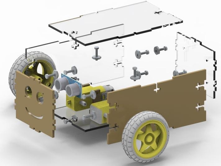
Figure 1 illustrates the physical structure of a car using an ultrasonic sensor, among other components.
The case developed in the car model was designed with the intention of accommodating the electric motors, the ultrasonic sensor, and the robot circuit control board.
The ultrasonic sensor, which will have the function of detecting the objects in front of you and allowing the control circuit to divert the robot from the detected obstacle.
In this article, you will understand the assembly of the car and its mechanical structure.
Therefore, through this article you will learn:
- Know the structure of the car using the ultrasonic sensor HC-SR04;
- Analyze the fixation of the mechanical structure of the car by means of screw and nut.
- Understand the importance of each part of the vehicle structure for the project as a whole.
- Build the PCBGOGO printed circuit board to control the robot.
- Download of the files to construct your mobile robot with Arduino
Now, we will start the complete presentation of the development of the C-SR04 Ultrasonic Sensor Car.
Development of robot car with Arduino to avoid obstaclesThis project consists of presenting a didactic model of a car using the ultrasonic sensor among other components, as well as the assembly of its mechanical structure.
The project is basically constituted by the physical structure of the car, responsible for containing the electronic components, which will process the signal to make the vehicle work.
Figure 2 illustrates the internal region of the car, as well as the screws responsible for fixing the side, front, rear, top and bottom surfaces of the vehicle.
Side brackets were designed to fix the motors, with holes sized for M3 nuts and screws.
The supports for the motors have a T-shaped structure, with the lower region responsible for locking the lower surfaces.
With this, the support passes through the lower region, being fitted in the region aligned with the two holes of the motor, and with that, when using the screw and the M3 nut, the developed support makes the motor stay fixed on the lower surface, preventing any type of oscillation during operation.
See the support illustrated in Figure 3.
In addition to the support for the two wheel motors, the T-inserts for the screws and nuts were modeled.
All fittings were designed for the type of M3 screw, with 6 fittings in all structures.
As the vehicle's structure is fitted, T-shaped cavities are modeled so that the screws and nuts are allocated, and thus, make the structure more rigid, as shown in Figure 4.
In the frontal structure, the cavities responsible for fixing the region that couples the ultrasonic sensor used were modeled, and for that purpose 6 M6 screws and nuts were used, two on each side, and one in the upper and lower region.
In the region where the sensor will be coupled, two holes were drilled at the ends of the sides for fixing the sensor to the structure, considering that all the vehicle's shape structures have a thickness of 3 mm.
In addition to all these features, a smile was also modeled, just like Figure 5.
The dimensioning of the vehicle was developed so that inside it was reserved a space that would be used to store the electronic devices necessary for its operation.
In this reserved compartment you can keep elements such as the battery, electronic board, or arduino, jumpers, among others, and your space was approximately in accordance with the specifications described in Figure 6.
The electronic board responsible for controlling the vehicle will be attached to the rear structure, in a vertical position, with 4 holes reserved for attaching it.
In the images used, most of the vehicle's structures were transparent in order to make internal viewing possible, leaving only some parts with a brown tint, to simulate the wood color, or the mdf material that could be used for its construction.
Figure 7 illustrates the entire vehicle structure in perspective exploded in a rendered image.
After assembling the project, it is necessary to install the PCBGOGO printed Circuit Board to control the robot vehicle with wheels.
PCBGOGO Printed Circuit Board to Control the RobotThis PCB was developed with PCBGOGO to control the complete functioning of the robot. Through it, you will be able to control the DC motor control driver and read the ultrasonic sensor.
In addition, we added a connection for a Bluetooth module. Thus, you will be able to control your robot through wireless commands.
The Printed Circuit Board structure is presented in Figure 8.
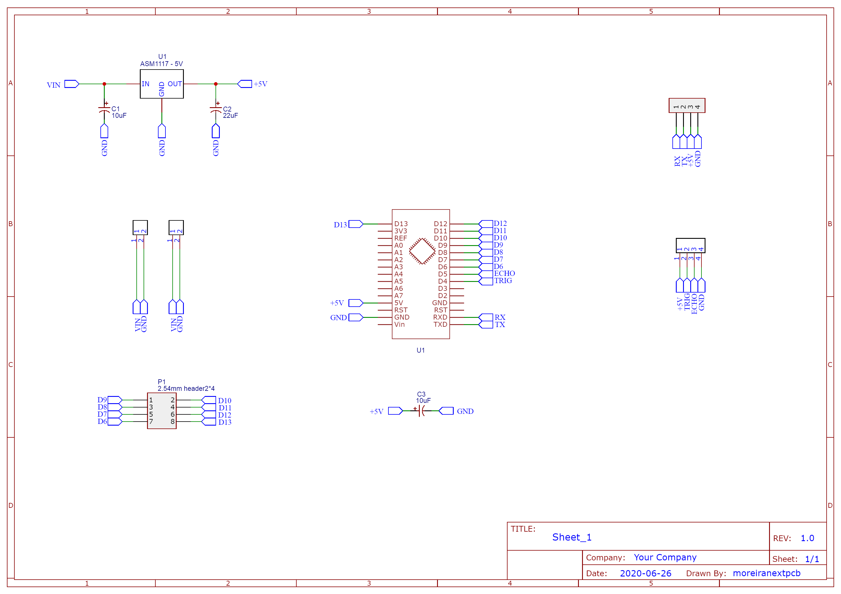
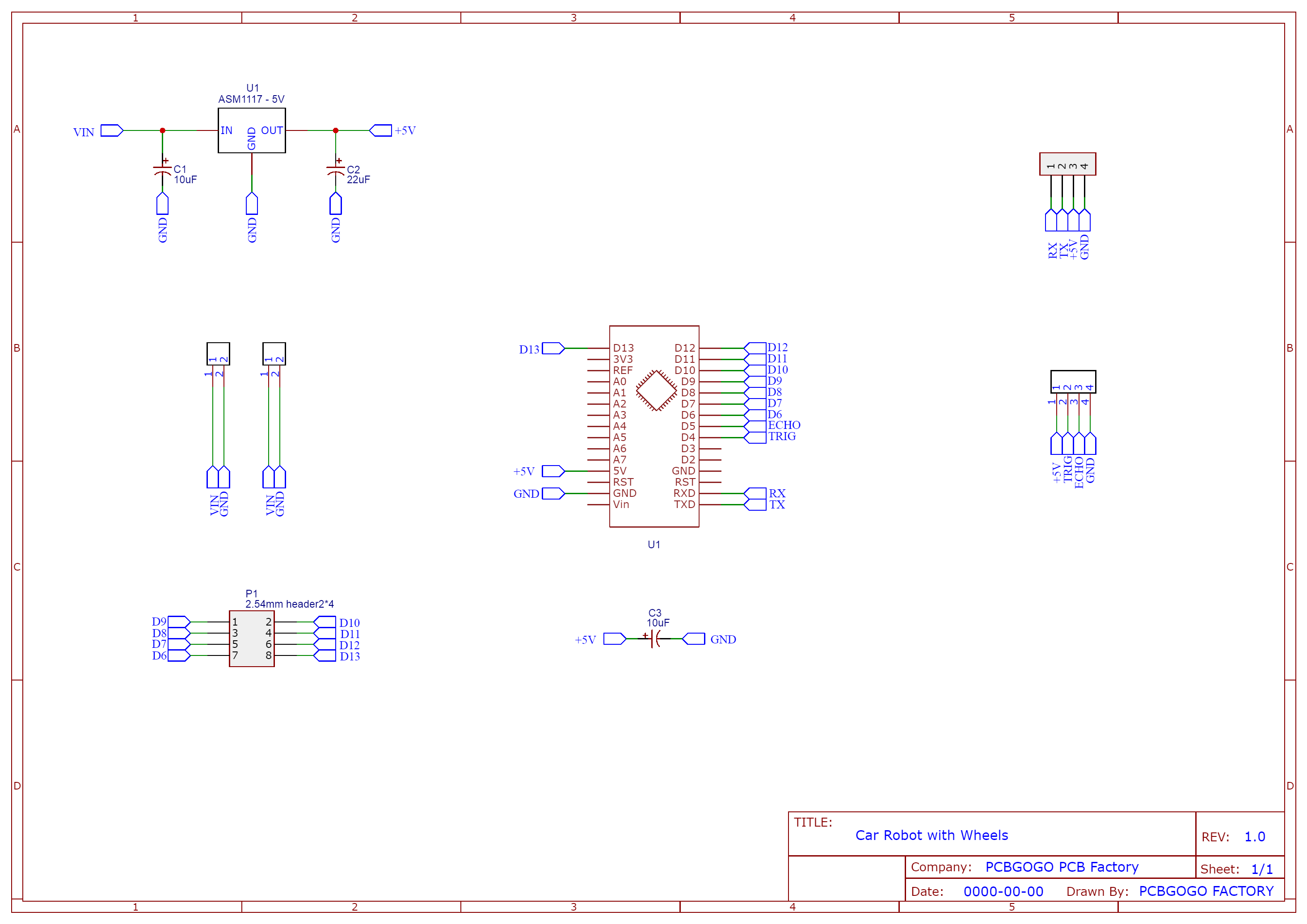
The PCBGOGO printed circuit board was developed from the electronic diagram below.
You can download the Gerber files and the STL files to construct your own car robot through the links presented below.
From these files, you can use the PCBGOGO website and use the $50 coupon discount and obtain your own PCB for the project.
ConclusionTherefore, from the development of this project, it was possible to analyze the vehicle's structure using the ultrasonic sensor, as well as its main structures.
It was verified that the entire structure of the vehicle has M3 screws for its fixation, and thus, creating better mechanical stability.
All its development was done with the purpose of making it as didactic as possible for its subsequent assembly with the electronic part because the vehicle structure was made by inserts.
With this, we conclude that each part of the vehicle structure was checked and analyzed in order to better understand the importance of correct assembly, observing the importance of each part.


_ztBMuBhMHo.jpg?auto=compress%2Cformat&w=48&h=48&fit=fill&bg=ffffff)


Comments
Please log in or sign up to comment.