

Hardware components | ||||||
 |
| × | 1 | |||
 |
| × | 1 | |||
 |
| × | 1 | |||
Software apps and online services | ||||||
 |
| |||||
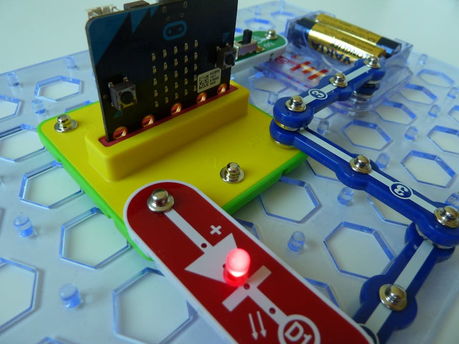
The snap:bit is an electronic component for the Snap Circuits educational electronic kit. It features a socket for connecting the BBC micro:bit. This allows the Snap Circuits to be programmatically controlled by the micro:bit.
This project demonstrates how to change the brightness of the connected Red LED (D1) by writing an analog signal to the micro:bit pin P1. Pressing button A decreases the brightness. Pressing button B increases the brightness.
This would work with any other LED components from the Snap Circuits kits.
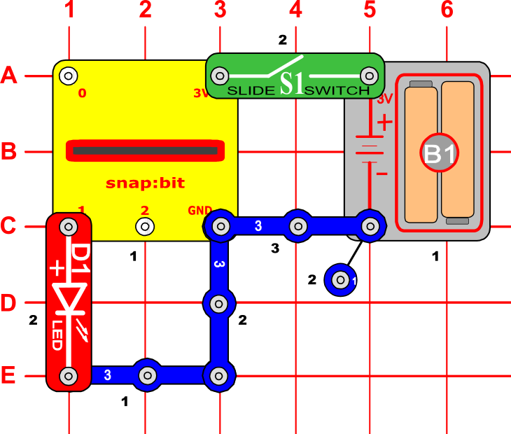
Snap Circuits diagramBuild the circuit shown in the diagram above.
CodeYou can build the code yourself in the MakeCode Editor. You will find the "analog write pin" block under the Advanced > Pins section.
Alternatively, open the ready project here: https://makecode.microbit.org/_T3m6EC7dMWcw
Once ready, download the code to your micro:bit. Then disconnect all cables from your micro:bit. Both the USB and the battery pack must be disconnected from the micro:bit.
How it works...When you close the slide switch (S1), the Battery Holder (B1) powers the snap:bit through the 3V snap and the micro:bit turns on. The “on start” event triggers and the micro:bit sets the brightness level to 5 and calls the “set brightness” function.
The “set brightness” function writes an analog signal to pin P1 to turn the LED on. The value of the analog signal determines how much current will flow from pin P1 to the LED. The more current flows, the higher the brightness of the LED is. The analog signal can take values between 0 and 1023. If analog signal 0 is written, the LED turns off. If analog signal 1023 is written, the LED lights in its full brightness. If a value like 128 is written then the LED lights in around half of its brightness.
Compare this to the digital signal used in the Turn LED on and off using the press switch project. Digital signal 0 is equivalent to analog signal 0, and digital signal 1 is equivalent to analog signal 1023.
The brightness of the LED does not depend on the current linearly, but rather exponentially. In other words, changing the analog value in the range between 0 and 200 is significantly more noticeable than in the range between 200 and 1023. Therefore, we use the brightness level as the exponent in this power of 2 formula:
Level 0 gives:
i.e. the LED is off.
Level 10 gives:
i.e. the LED is at its full brightness.
This table shows how the brightness level is converted to the value of the analog signal sent to pin P1:
The “set brightness” function uses the above formula to convert the current brightness level (the “level” variable) to the analog value to be written to pin P1. The “set brightness” function also plots the current brightness level to the LED screen of the micro:bit as an extra visual indication.
Pressing button A on the micro:bit decreases the current brightness level by 1 and calls the “set brightness” function to update the brightness of the LED. Note the “if” statement that limits the minimum brightness level to 0.
Pressing button B on the micro:bit increases the current brightness level by 1 and calls the “set brightness” function to update the brightness of the LED. Note the “if” statement that limits the maximum brightness level to 10.


Comments
Please log in or sign up to comment.