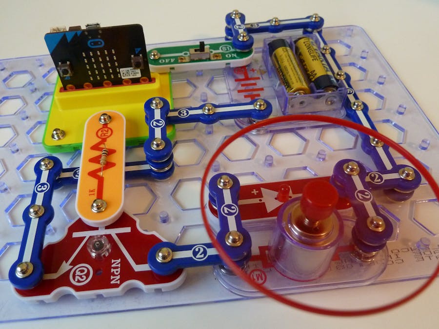
The snap:bit is an electronic component for the Snap Circuits educational electronic kit. It features a socket for connecting the BBC micro:bit. This allows the Snap Circuits to be programmatically controlled by the micro:bit.
This project demonstrates how to control the DC Motor (M1) of Snap Circuits with the BBC micro:bit.
The P0, P1, and P2 pins of the micro:bit can drive just a few mA of current, which is enough to power low-current devices like LEDs. However, most other devices consume a larger current. The DC Motor (M1) can consume 100 mA or more of current, which cannot be delivered by the micro:bit pins.
Therefore, the motor must be powered directly from the batteries, yet connected to the micro:bit to control its on and off state. We will use the NPN Transistor (Q2) as a switch to turn the motor on and off by applying a small amount of current from the micro:bit to the transistor's base.
This project is very similar to the Control Lamp with Micro:bit and Transistor with the exception of adding a flyback diode. Wondering what a flyback diode is? Keep reading! It will be explained at the end of this project.
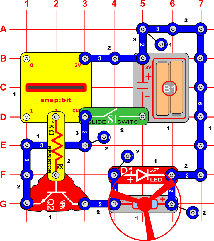
Snap Circuits diagramBuild the circuit shown in the diagram above.
CodeYou can build the code yourself in the MakeCode Editor. You will find the "digital write pin" block under the Advanced > Pins section.
Alternatively, open the ready project here: https://makecode.microbit.org/_8pFPz9ViMWaM
Once ready, download the code to your micro:bit. Then disconnect all cables from your micro:bit. Both the USB and the battery pack must be disconnected from the micro:bit.
How it works...When you close the slide switch (S1), the Battery Holder (B1) powers the snap:bit through the 3V snap and the micro:bit turns on.
At this moment no current flows from pin P2 of the micro:bit to the base of the NPN transistor (Q2). Therefore, no current flows between the collector and the emitter of the transistor, so that part of the circuit is open and the DC Motor (M1) is off.
Press and release button A on the micro:bit. The "on button A pressed" event triggers and the micro:bit writes a digital 1 signal to pin P2. This closes the circuit between the P2 and GND pins and a small current starts flowing to the base of the NPN transistor, through the transistor's emitter, the GND pin of the snap:bit, and back to the negative terminal of the Battery Holder (B1).
The 1kΩ Resistor (R2) limits the current flowing to the base of the transistor to a very small amount - around 1 mA. The transistor would be damaged if a large current flows through it. The resistor protects the transistor from this risk.
The small amount flowing through the base of the transistor is enough to trigger the current flow from the collector to the emitter. A large amount of current (up to 200 mA) starts flowing from the positive terminal of the Battery Holder (B1), through the DC Motor (M1), the collector and the emitter of the transistor, the GND pin of the snap:bit, and back to the negative terminal of Battery Holder (B1). The part of the circuit connected to the motor is now closed and the motor turns on.
Press and release button B on the micro:bit. The "on button B pressed" event triggers and the micro:bit writes a digital 0 signal to pin P2. This opens the circuit between the P2 and GND pins and the current stops flowing to the base of the transistor. This stops the current flow from the collector to the emitter of the transistor and the motor turns off.
The flyback voltage and the flyback diodeAt this point, you may wonder what is the purpose of the LED (D1) that is connected across the DC Motor (M1)? Have you noticed that the LED flashes for a fraction of the second when you stop the motor?
Inside the DC Motor (M1) is a coil of wire. If a large electric current flows through the loops of the wire, a magnetic field is generated, concentrated enough to move a small magnet. Such a magnet is attached to the shaft of the motor, and so the motor's shaft spins.
If the electric current to the motor suddenly drops, the coil inside generates a short pulse of a very large voltage, known as the flyback voltage. If there is no other way for this high-voltage pulse to dissipate, it will go through the NPN Transistor (Q2) and it may destroy it.
Therefore, we add the LED across the motor in the direction as shown in the diagram. It creates a circuit loop for the high-voltage pulse to go back to the coil of the motor and protects the rest of the electric circuit.
Used this way, this LED is also known as a Flyback Diode. The short flash you see is actually the flyback voltage that goes through it.


Comments
Please log in or sign up to comment.