
Hardware components | ||||||
 |
| × | 1 | |||
 |
| × | 1 | |||
 |
| × | 1 | |||
Software apps and online services | ||||||
 |
| |||||
The snap:bit is an electronic component for the Snap Circuits educational electronic kit. It features a socket for connecting the BBC micro:bit. This allows the Snap Circuits to be programmatically controlled by the micro:bit.
This project demonstrates how to automatically change the brightness of the LED in a way to simulate a smoothly pulsing LED.
This project builds on top of what we learned in the Blinking LED and the Adjust LED brightness projects.
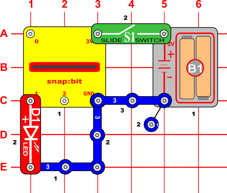
We will program the BBC micro:bit to automatically change the current on pin P1, so the connected Red LED (D1) of Snap Circuits is pulsing smoothly.
Snap Circuits diagramBuild the circuit shown in the diagram above.
CodeThe code in this project uses the "forever" cycle to continuously repeat the instructions in the cycle's body. They change the analog signal written to pin P1 (where the LED is connected to) between the minumum "0" and the maximum "1023" in a very short interval.
You can build the code yourself in the MakeCode Editor. You will find the "analog write pin" block under the Advanced > Pins section.
Alternatively, open the ready project here: https://makecode.microbit.org/_1xveM9M5L0ae
Once ready, download the code to your micro:bit. Then disconnect all cables from your micro:bit. Both the USB and the battery pack must be disconnected from the micro:bit.
How it works...When you close the slide switch (S1), the Battery Holder (B1) powers the snap:bit through the 3V snap and the micro:bit turns on. The “on start” event triggers and the micro:bit sets the brightness level to 0 and the increment step to 1.
When the “on start” event finishes, the “forever” loop starts. It changes the brightness level by the increment step. In the beginning, the increment step is 1, which means that the brightness will increase with one level. Then it writes an analog signal to pin P1, calculated using this formula:
where n is the current brightness level (see the Adjust LED brightness projects for details). This changes the current flow between the P1 and GND pins. The LED changes its brightness based on how much current flows. The loop now pauses shortly for 50 milliseconds.
Next, the “forever” loop checks if the current brightness level reached a maximum of 10. In such a case, it changes the increment step to -1, which starts decreasing the current brightness with one level on each iteration of the “forever” loop. When the current brightness level drops down to 0, the increment step changes back to 1. In addition, the loop pauses for half a second (500 ms) for a better pulsing effect.
The “forever” loop executes the instructions in its body again and again until the micro:bit is turned off. So does the pulsing.
Try experimenting by changing the duration of the pause after the “analog write” instruction. How does the pulsing change if you set the pause to:
- 10 ms
- 200 ms?


Comments
Please log in or sign up to comment.