

Hardware components | ||||||
 |
| × | 1 | |||
 |
| × | 1 | |||
 |
| × | 2 | |||
 |
| × | 2 | |||
 |
| × | 1 | |||
| × | 1 | ||||
| × | 3 | ||||
 |
| × | 1 | |||
Software apps and online services | ||||||
 |
| |||||
 |
| |||||
Let us the take the story of Mr. Nigel. Suppose he is sleeping peacefully one night. The adjacent two rooms are stored with sophisticated electronic gadgets. If the room temperature of either of the rooms crosses a threshold value, it sends an immediate push notification to Nigel's phone alerting him to go to the rooms and physically check out what is wrong. So he enters the passage connected to the two rooms and it's dark, and switches are beyond the reach of his hand. So he simply pulls out the phone from his pocket and uses Google Assistant to turn on the lights of the rooms.
Which lights would turn on is solely up to Mr. Nigel's discretion. Since the device uses Machine Learning concept of Polynomial Regression to predict the future room temperatures, he can decide whether he should stay or go to bed based on the data.
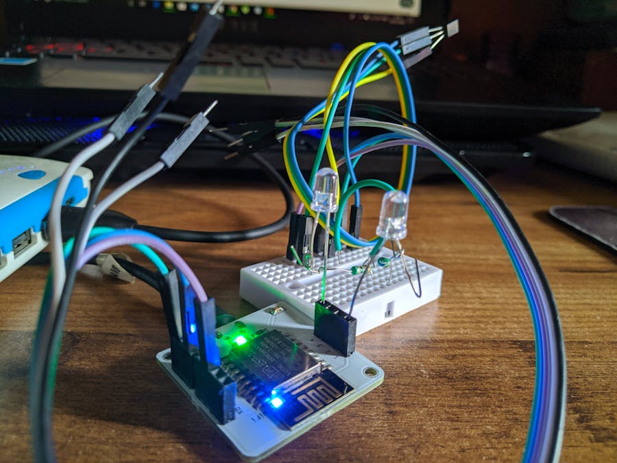
Step 1: Hardware Setup- One end of the green, blue and purple connecting wires are connected to the pins 5V, GND and A0 respectively. The other end is connected to the Mini Breadboard.
- For connecting the LM35 Temperature Sensor, the VCC, the Output and the GND is connected to FEMALE TO MALE wires of color code blue, green and yellow respectively.
- So in the breadboard, the blue, green and yellow of FEMALE TO MALE wires are connected to the green, purple and blue of the CONNECTING WIRES (JUMPER WIRES) respectively.
- For this project I have used GPIO pin number 1 (Connected to Yellow LED) and pin number 4 (Connected to White LED). A 330 Ohm resistor has been used in series individually for each pin.
For this project I have used my power bank to power the Bolt Module. The code is written entirely in JavaScript.
Select the A0 pin since that is the output pin we are going to use for LM35. Give a variable name "temp".
Next for the code:
setChartLibrary('google-chart');
setChartTitle('Polynomial Regression');
setChartType('predictionGraph');
setAxisName('time_stamp','temp');
mul(0.0977);
plotChart('time_stamp','temp');NOTE: I have used a sensor value of 275 which is basically 26.86 Degree Celsius
After this is done go the product page, select the product, click on Deploy Configuration and view.
Now this is the most crucial step. For this I would request to go through the Steps numbered 2, 3 and 4 of the following link for the basic understanding of the concepts.
LINK: https://www.hackster.io/nitro/5-minutes-4-steps-and-ok-google-turn-on-the-lights-cedc45
Apparently this project inspired me to implement this idea.
However there are two LEDs for my project. Each of which can be switched ON and OFF. So for me 4 Different URLs were required.
- For ON and OFF of LED 1 (Yellow LED).
- For ON and OFF of LED 2 (White LED).
The fundamental point to be remembered here is that, in cases of Applets which demanded to use the both LEDs simultaneously, the phrase command which is given to Google Assistant and also the reply from the Assistant needs to be the EXACT SAME.
- So for the command "Turn ON Both LED", I have used two different URLs which sets the state of pin 1 and pin 4 as HIGH.
- And for the command "Turn OFF Both LED", I have used two different URLs which sets the state of pin 1 and pin 4 as LOW.
NOTE: Basically it must be noted that both Bolt Alert system(using Push Notifications) and also the IFTTT Google Assistant and Webhooks Applet implements the basic concept of "if-else" condition, which is a very common logical condition in the programming world.
Following are some pictures taken while the product was in use:
The Google Drive link of my Project video is given here:
https://drive.google.com/folderview?id=1N2fCxdZBL5O6wmiPdqr_Gtye3qX5ZI0b


Comments
Please log in or sign up to comment.