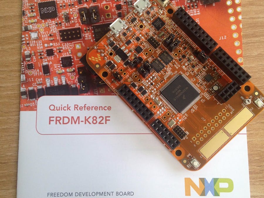
- 150 MHz ARM Cortex-M4F
- 256 KByte SRAM
- 2x 32MBit (4 MByte) QSPI memory
On the right there are two rows of FLEXIO headers . On the left side of the CPU there are two QSPI Memory devices (2x32MBit).
Has the push buttons, RGB LED, accelerometer/magnetometer, …
Beside of the Arduino headers, there are capacitive touch pads, header for serial bluetooth module, header for nRF24L01+ transceiver.
A factory-installed RGB LED demo is running on the board:
Now lets get started with installation of necessary software.
Step 1download the IDE at Kinetis design studio
Build custom SDK and Download the SDK. Select Free RTOS
Build custom SDK here
Download and install the : DRIVER (Windows OS)
Install the driver by plugging in the board.
STEP 4To make the serial port as 'Opensda CDC Serial Port', we have to download a binary file and bootload it to the FRDM K82F Dev Board. Converting it to Opensda has its own advantages, we can easily upload the code to the FRDM board.
Binary file OpenSDA V2.1 Bootloader can be downloaded from HERE at the bottom of the page.
STEPS TO BOOTLOAD THE BOARD TO OPENSDA:
- Plug in the board by pressing the reset button.
- Drag and drop the binary file in the BOOTLOADER(H): disk drive.
- Unplug the board.
Watch the Videos here to see all the steps above mentioned and also to learn how to build and run code.
The setup is now complete. Lets see how to run a sample program. For that download a serial software like Coolterm.
- Open Kinetis studio IDE
- Import a demo project from list of demo apps in Kinetis SDK folder
- Build the project by clicking on Hammer icon
- To debug install jlink open SDA ( see this video)
- open a serial software like coolterm ( baud rate 115200)
- Configure debug options and start debug
See the ouput on coolterm.
To edit the program go to C/C++ view and edit the program.
You have successfully compiled and debugged your first kinetis Sdk Application.
Cheers


Comments
Please log in or sign up to comment.