[Updated to include official full-fledged Dr. Wattson Python library]
[Update: Dr. Wattson Energy Monitoring Board V2 is now available! See "Things" used for link to the board]
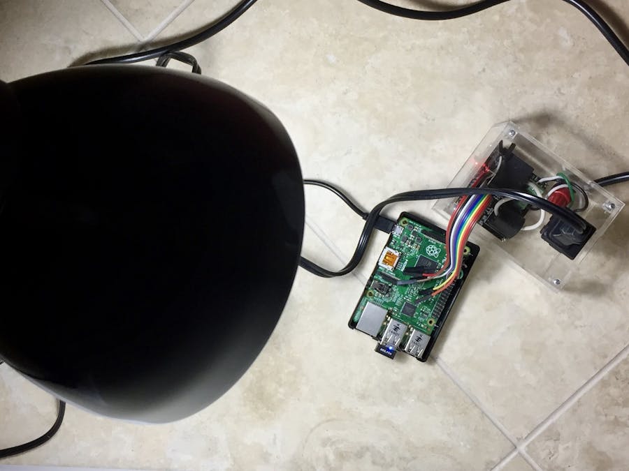
In this article, I explain how I integrated Dr. Wattson with Raspberry Pi and AWS IoT to create an Internet-connected Energy Monitor.
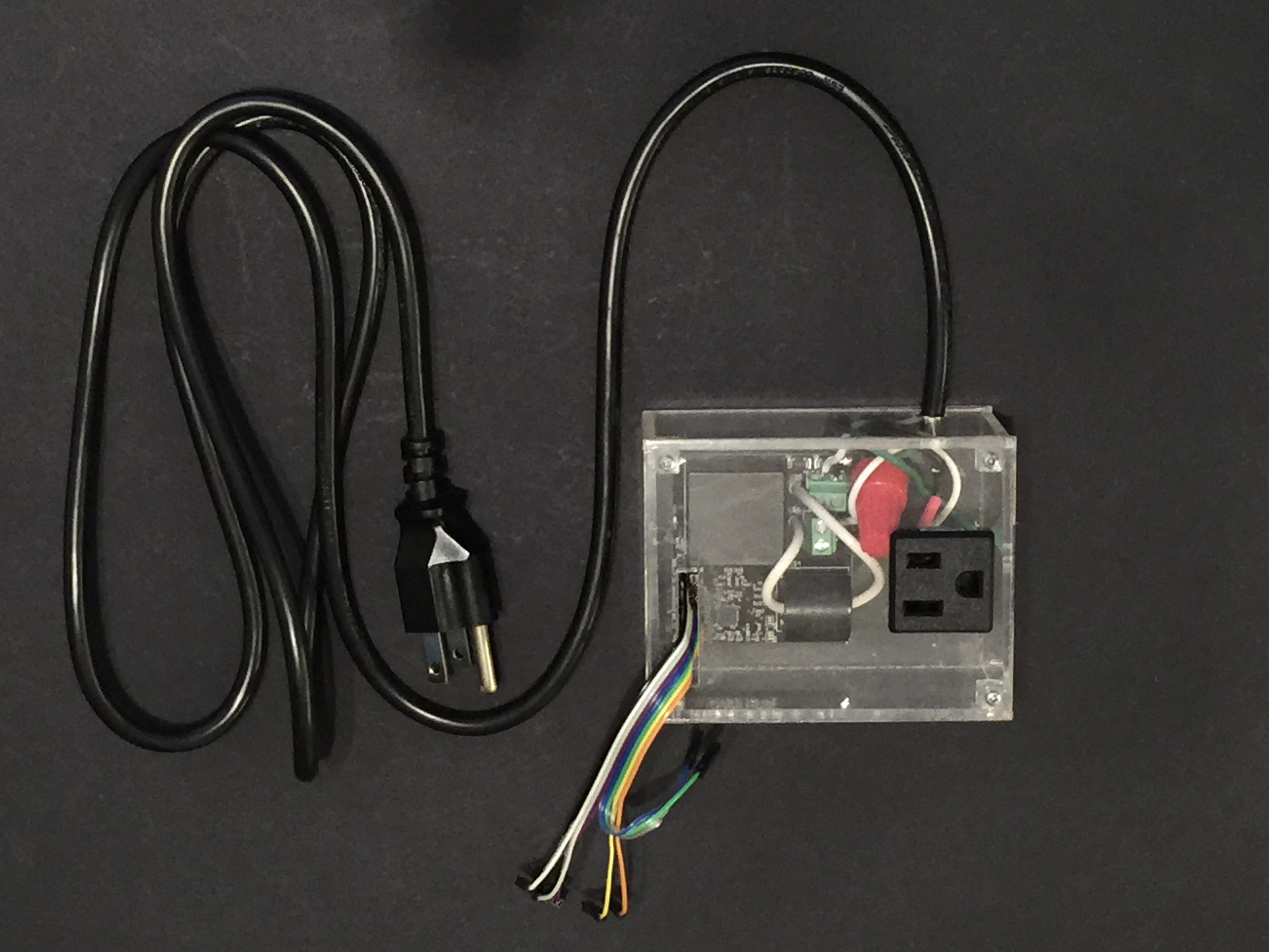
Dr. Wattson is an energy monitoring board from Upbeat Labs, using Microchip’s MCP39F521. It comes calibrated, doesn’t need any additional parts, and offers highly accurate data over a large range. It is coupled with Arduino and Python libraries to enable quick and easy access to energy consumption data, so you can integrate into your own applications and solutions without worrying about the nitty-gritty of measuring energy consumption or dealing with AC current directly. I wrote another article on how I integrated with the Arduino — you can read about it here.
Dr. Wattson is designed with bi-directional level shifters, so it can just as comfortably talk to 3.3v systems like Raspberry Pi, as it can with 5v systems like Arduino.
I was interested in testing it out with a Raspberry Pi and setting in motion the first rumblings of a Raspberry Pi library for Dr. Wattson. WiringPi seemed like a good candidate, but I was interested in a Python library, as Python is a very popular programming environment, especially on the Raspberry Pi. I decided to use the Python smbus library.
[Dr. Wattson's official Python library was released on Sept 2018, making it easier to use, and supporting ALL of the functionality of Dr. Wattson! See GitHub link below]
In the rest of this post, I’m going to describe how I:
- connected the Raspberry Pi to Dr. Wattson
- enabled I2C on the Pi
- used the Python smbus library to initiate I2C communications with Dr. Wattson and get some data, and created the first Raspberry Pi Python library for Dr. Wattson
- integrated with AWS IoT on the Pi, so I could send the data over to AWS.
- accessed that data on my laptop using MQTT.fx client talking to AWS IoT.
You can also access that data on, say, a mobile app that integrates with AWS IoT. However, I just used an MQTT Client on my laptop to demonstrate the remote connectivity. I was able to access the data in near real-time from the cloud, by subscribing to the updates that my Pi was providing.
Step 1: Enable I2C on the PiThe first step was enabling the I2C bus on the Pi. Note that I am using Raspbian Stretch, which is the latest distribution. The easiest way to do so was to launch the config utility from the desktop.
You will need to reboot the Pi for the changes to take effect.
From the command line, you can also launch “sudo raspi-config” to enable I2C. If you are a bored hacker, you can modify the requisite files on the filesystem yourself — you obviously don’t need to hear it from me!
The Raspbian Stretch OS comes preinstalled with the necessary packages for I2C communications, so you don’t need to do anything further. If you are using an older version (Jessie or Wheezy), you may need to install some additional packages. There are many tutorials on the web for this step, so I’m not going to go into the details here.
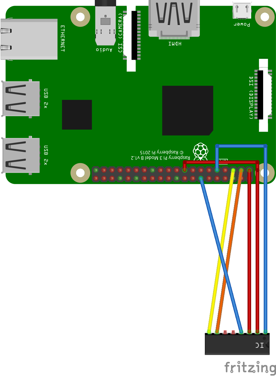
Step 2: Connect Dr. WattsonThe next step was to actually hook up Dr. Wattson to my Raspberry Pi. Here is a Fritzing diagram showing the connections.
I really did not have the time and patience to model Dr. Wattson as a new part in Fritzing, so I cheated, and used the advice of Z-HUT to easily whip up a custom part without much ado. I highly recommend watching it! https://www.youtube.com/watch?v=dfxx8wF3Uhs — thanks Z-HUT!
The only downside is that I have to be content to use the image of the “generic IC” part that I modified to represent Dr. Wattson. C’est la vie!
Here is the wiring, from left to right:
- SCL to RPI (physical) pin 5 (SCL)
- SDA to RPI (physical) pin 3 (SDA)
- ZCD pin not used
- Event pin not used
- GND to RPI (physical) pin 14 (GND)
- Vin to RPI (physical) pin 1 (3.3v)
- 3.3v to RPI (physical) pin 17 (3.3v)
- GND to RPI (physical) pin 9 (GND)
Next up, I used i2cdetect -y 1 to test the connection. Dr. Wattson uses (by default) an I2C address of 0x74.
[Note: you can configure the addressing using two solder jumpers on the board, for a total of 4 possible combinations (that correspond to addresses of 0x74, 0x75, 0x76 or 0x77). This means that you can connect up to 4 Dr. Wattson boards using a single MCU]
pi@raspberrypi:~ $ i2cdetect -y 1
0  1  2  3  4  5  6  7  8  9  a  b  c  d  e  f
00:          -- -- -- -- -- -- -- -- -- -- -- -- --
10: -- -- -- -- -- -- -- -- -- -- -- -- -- -- -- --
20: -- -- -- -- -- -- -- -- -- -- -- -- -- -- -- --
30: -- -- -- -- -- -- -- -- -- -- -- -- -- -- -- --
40: -- -- -- -- -- -- -- -- -- -- -- -- -- -- -- --
50: -- -- -- -- -- -- -- -- -- -- -- -- -- -- -- --
60: -- -- -- -- -- -- -- -- -- -- -- -- -- -- -- --
70: -- -- -- -- 74 -- -- --
All systems ok at this point!
Step 4 : Using Python and smbus library[Update - The official Python library for Dr. Wattson was released on September 2018. It is available on GitHub and has instructions for usage along with tons of example programs. The link to the GitHub repository is included below].
Optional: If you aren’t interested in how I got started with building my Dr.Wattson Python library for Raspberry Pi, you can skip this and move on to Step 5.
I was struck by the paucity of documentation when it comes to actually using I2C on the Raspberry Pi. Python SMBus has some very sparse documentation. Contrast that with the Arduino that has plenty of documentation and examples for creating your own libraries.
However, after a bit of experimentation, I managed to get the communications and initial data working. So that means that once the library is fully developed, you won’t have to deal with sucky documentation and the idiosyncrasies of I2C on the Pi!
Here is the gist:
import smbus
bus = smbus.SMBus(1)
data = [0x08, 0x41, 0x00, 0x02, 0x4e,28 , 0]
checksum = 0xa5
for x in data:
 checksum += x
 data[6] = checksum % 256
res = bus.write_i2c_block_data(address, 0xa5, data)
time.sleep(0.05)
buf = bus.read_i2c_block_data(address, 0x4e, 31 )
I mainly used write_i2c_block_data and read_i2c_block_data, to read from the appropriate registers and get the requisite data. The trick was in figuring out the right arguments. However, I also had to do an extra read_data() in order to get the correct data. It appears as though there is some disconnect between the smbus library and the MCP39F521 in the protocol expectation — I will still need to debug this further and figure out why exactly.
Step 5: Using MCP39F521 libraryUsing the above rudimentary stuff and the datasheet for the MCP39F521 to use the appropriate commands and registers, and building the bytestream back into proper data, I created the beginnings of my MCP39F521 library. I have not decided all the data structures and objects yet — I’m currently returning the result of the call to read the energy data as a dictionary (final form TBD). Here it is in action:
#!/usr/bin/python
import MCP39F521
wattson = MCP39F521.MCP39F521()
while(1):
    result = wattson.readMCP39F521()
    print "VoltageRMS = " + str(result['VoltageRMS'])
    print "CurrentRMS = " + str(result['CurrentRMS'])
    print "LineFrequency = " + str(result['LineFrequency'])
    print "ActivePower = " + str(result['ActivePower'])
    print "ReactivePower = " + str(result['ReactivePower'])
print "ApparentPower = " + str(result['ApparentPower'])[Update: Final form of return results has been determined. Please see the Python library in the GitHub link below]
Step 6: Using AWS IoT with Raspberry PiThere is a lot of information available regarding setting up AWS IoT, so I’m not going to reinvent the wheel here, but rather describe the process from a very high altitude — the 30,000 foot view.
I’m using the AWS IoT Python SDK, which you can get from here: https://github.com/aws/aws-iot-device-sdk-python
It has instructions on installation and setup. Raspbian Stretch meets the minimum requirements. I installed the SDK using pip.
pip install AWSIoTPythonSDKI then set up the necessary certificates and endpoints for use, creating a “Thing” in my device Registry (that I aptly call DrWattson), and using that information to run the example (more on that below).
Step 7: Tying it all togetherI took the “basicShadow” example from above GitHub link, and made some modifications — first of all, I want to send the “reported” state in a loop, so I changed the JSON payload to send the “reported” state as opposed to the “desired” state (since this example is run on the sensor device reporting the data, as opposed to setting the “desired” state from a client). I also don’t need a callback to be invoked when doing the shadowUpdate (in the example, it calls customShadowCallback_Update), so I set that parameter to “None”.
Here is my change:
... unchanged stuff
import MCP39F521
... unchanged stuff
# Update shadow in a loop
loopCount = 0
wattson = MCP39F521.MCP39F521()
while True:
    result = wattson.readMCP39F521()
 JSONPayload = '{{"state":{{"reported":{{"voltageRMS":{0}, "currentRMS":{1}, "lineFrequency":{2}, "activePower":{3}, "reactivePower":{4}, "apparentPower":{5} }} }} }}'.format(result['VoltageRMS'], result['CurrentRMS'], result['LineFrequency'], result['ActivePower'], result['ReactivePower'], result['ApparentPower'])
    print JSONPayload
    deviceShadowHandler.shadowUpdate(JSONPayload, None, 5)
    loopCount += 1
    time.sleep(1)
I ran it, like so: (where the rootCA, certificate and private key files are downloaded from AWS IoT after “Thing” creation).
python awsIoTExample.py -e <endpoint> -r </path/To/RootCAcert> -c </path/to/thingcert> -k </path/to/thingPrivateKey> -n <ThingName>The program keeps polling the Dr.Wattson board for energy data, and then sends that data to the AWS IoT service. You can adjust how often you want to poll and send the data. The nice thing about the MCP39F521 is that it has energy accumulators which you can turn on. If all you want to measure is the accumulated energy data, you can reduce the frequency of updates to AWS. You can even make it configurable, by adding a “desired” property — “updateInterval”, to your JSON payload. That way, the client (mobile app or MQTT client as the case may be) can request the desired update interval (smaller interval if you want to see real-time data right away, or larger interval if you want to monitor overall profile at a coarser grain). You can add additional “desired” properties — “energyAccumulatorOn”, for example, to be able to turn on/off the energy accumulator from your client. Those changes will turn it from being purely a reporter of data, to being one whose properties and behavior you can change at runtime, remotely.
I then connected an MQTT client (I used MQTT.fx) to the AWS IoT endpoint and subscribed to updates coming from AWS IoT to be able to see the data coming from my Dr.Wattson board and Raspberry Pi, remotely and in near real-time.
You can also set up an AWS IoT Rule to insert that data into DynamoDB, and now you can have historical energy consumption data for whatever load you are trying to measure. You can then use some Javascript charting libraries (I really like AmCharts) to visualize your energy data by connecting to your DynamoDB directly and retrieving the data from there! (Possibly the topic of another post?)
Step 8: View the data on MQTT.fx clientSetup the connection to AWS IoT on MQTT.fx. Use the certificates you download after you create your “Thing” on AWS IoT.
Connect to the AWS IoT endpoint corresponding to your setup.
Subscribe the “Thing Shadow” updates :
— “$aws/things/THINGNAME/shadow/update/accepted”See the updates happening in near real-time! (depends on network latency, of course). Every time the Pi publishes an update (sends the polled Dr.Wattson energy values to AWS IoT), the MQTT.fx client will receive the message as it has subscribed for updates.
This exercise shows the integration of Dr. Wattson with Raspberry Pi and AWS IoT and displaying the data remotely using MQTT.fx client. I2C on Raspberry Pi, especially Python SMBus library is quite sparsely documented. However, I managed to start the rumblings of a Dr.Wattson Python library for Raspberry Pi, and also integrated AWS IoT into the mix*. With the Dr. Wattson library and the AWS IoT example, this step was quite easy to do.
[* Full-fledged Python library is now available!]
I now have an internet-connected Watt Meter, which comes calibrated right out the box, is highly accurate and is dead easy to use with the library, as demonstrated above. With a little more work, you can have a mobile app getting and displaying the updates on your phone, instead of on MQTT.fx!
With Dr. Wattson, you can make your own internet-connected Watt Meter. Or add energy monitoring into your own wild and crazy idea, whatever it might be — Dr. Wattson is a building block for your use. [Update - Dr. Wattson is now available! :-) ] Get more information and Sign up for news and updates here!
Cheers,
Sridhar


Comments
Please log in or sign up to comment.