An Arduino based crawler/tank!? Haven't we already seen dozens of them? Maybe, but not such a variant. The focus is lesser about the crawler and more about communication between electronic control units (ECUs) based on Controller Area Network (CAN) as used in current automobiles.
UPDATES:
- Implementation updated for both boards
- A couple of fixes inlcuded to increase stability for I2C and TOF (took quite a while)
- Reduced the CPU frequency of the D-duino32 from 240 to 160 MHz (reduced heat emission and more important power consumtion in order to lesser stress the supply)
- Learning A: Don't try to read more than every 50ms the TOF sensor (fixed freezes)
- Learning B: Don't read to quickly from I2C devices (fixed instabilities by 10ms delay)
- ESP32-CAM with folding device included (it's more a gimick rather a feature, it only shares the 5V power supply from DC regulator, but it's not connected to CAN)
- Learning C: If the video of the ESP32-CAM is disturbed, check if sufficient power is supplied (on-board 5V from Wemos D1 R32 was insufficient)
ESP32 Crawler with camera at the front and CAN transceivers below the chassis
Fore sure: First off, we need a vehicle - messing around on CAN in a real car isn't a good idea - and some spare parts from my loot boxes. I picked up a tracked chassis with 2 motors from DOIT (T101 mini), a Wemos D1 R32, a D-duino32 with on-board OLED, a motor shield from Adafruit, a TOF sensor (VL53L0X) for distance measurements, an IMU (MPU9250) for tilt detection, a battery box, some screws & nuts, jump wires and last but not least two CAN transceivers (SN65HVD230). After a small while everything was assembled. So let's have a look what came out of the spare time activity...
But what is now about the CAN communication? Before we have a closer look at it, I would like give an overview about the wiring used for this build. Here the major focus is the high-speed (HS) CAN connection - whereby "high-speed" tells us more about the electrical behaviour rather than the baudrate. The ESP32 has got an integrated HS CAN controller, so we just need to hook up a matching CAN transceiver on both MCUs, compare here.
Wiring with optinal camera modul
The used SN65HVD230 transceivers need to be powered by 3.3V and are using the same as signal level. They are going to be connected from their CRX and CTX to GPIOs of the MCUs (no cross-over). Afterwards both are connected to each other via CANH and CANL (no cross-over). Motor shield, TOF/IMU sensor are connected to the D1 R32 by I2C (SDA & SCL). The battery box and motors are connected to the shield and finally the D-duino32 is power by the help of a DC regulator (AMS1117-5.0V). I tried it by using V5 & GND from D1 R32, but struggled a lot with strange behaviours (especially about the CAN communication). After applying battery power by the help of the regulator directly to the D-duni32, the problems were gone. I guess the voltage regulator of the D1 R32 is just not capable enough to drive the shield, sensors plus the D-duino32.
The comminication over CAN between the ECUs happens by frames. Here I used the standard format which uses up to 8 bytes per message as payload. If you are interrested how the bus abritration per ECU is handled and how the complete frame formate looks like, please have a look here. The messages (or frames) are differentiated by network-wide unqiue IDs. This ID is also equivilant with a priority (smaller ID has higher priority in case of concurrent abritration). So already by creating a message catalog some care is needed also for the order of IDs and not only payload.
CAN messages between both nodes
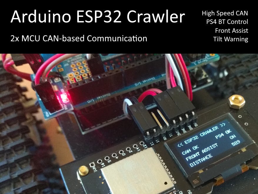
In the project IDs 0x10, 0x11 and 0x12 are used to transfer the information from the PS4 controller connected to D-duino32 over CAN to D1 R32 which calculates the steering/throttle and finally the left and right motor speed from it. Vise versa D1 R32 sends a messages with ID 0x20 containing a status of the front assistant system (autonomious breaking based on distance in front collected by the TOF sensor), status of tilt warning system (pitch and/or roll > 45° gathered by IMU). Status information is shown on the OLED and used to control the PS4 LED and rumble function for a direct feedback to the "driver".
void task_txCAN(void * pvParameters) {
 for(;;) {
   CAN_frame_t tx_frame;
   int d = distance;
   tx_frame.FIR.B.FF==CAN_frame_std;
   tx_frame.MsgID = 0x20;
   tx_frame.FIR.B.DLC = 8;
   tx_frame.data.u8[0] = byte(auto_break);
   tx_frame.data.u8[1] = byte(break_active);
   tx_frame.data.u8[2] = byte(tilt_warn);
   tx_frame.data.u8[3] = 0;
   tx_frame.data.u8[4] = byte(d>>(3*8));
   tx_frame.data.u8[5] = byte(d<<(1*8)>>(3*8));
   tx_frame.data.u8[6] = byte(d<<(2*8)>>(3*8));
   tx_frame.data.u8[7] = byte(d<<(3*8)>>(3*8));
   ESP32Can.CANWriteFrame(&tx_frame);
   delay(50);
 }
}
Often an information needs to be converted in order to be transfered by bytes in a frame. This could happen by converting e.g. a bool to a bit (if there is no shortage, you can also use a byte). More care is need for other data types and even more how those data types are represented on a specific MCU. As example: An Arduino Uno is using 2 bytes for an integer (16-bit), but the ESP32 is using 4 bytes (32-bit). Special care is needed if different MCU architectures are mixed in a network and how the data type representation for each of them is looking like. Therefore it's important to know how the message catalog looks like and how presenatation rules for the payload need to be handled.
Connected Arduino Due for monitoring
For analyzing/monitoring the traffic between D1 R32 and D-Duino32, I used an Arduino Due which also owns an integrated CAN controller. The Due - different from EPS32 - supports not only one but two channels, so you can connect two transceivers and e.g. listen to two different CAN network segments. Quite handy if a gateway needs to be analyzed, but not needed in this project. Here is one simple segment between only two MCUs all we need. The transceiver of the Due can simply be hooked up on CANH and CANL to the existing wiring, because CAN is a bus and not a point-to-point connection.
Log of the traffic between both ESP32s
The Due receives all messages on the bus (there is no filter applied to it) and acts as read-only spy. The received frames are printed to USB serial and on a PC PuTTY is used to log them.
Long story short: I hope you had some fun while reading through this article. But now let's have a ride with the crawler in the living room... CAN I do?!
ESP32 Crawler and PS4 controller (green LED of controller indicates active front assist)
Here are some more impressions with the camera add-on board. The camera is using the example implemenation from the Arduino ESP32 SDK. Only change to it was to use WiFi AP instead of STA. Now the camera opens an own access point where a mobile phone can connect to. On my Android phone, I used Chrome to show the HTML page with embedded video stream.
ESP32-CAM add-on board and IMU MPU9250 close up


_3u05Tpwasz.png?auto=compress%2Cformat&w=40&h=40&fit=fillmax&bg=fff&dpr=2)
Comments
Please log in or sign up to comment.