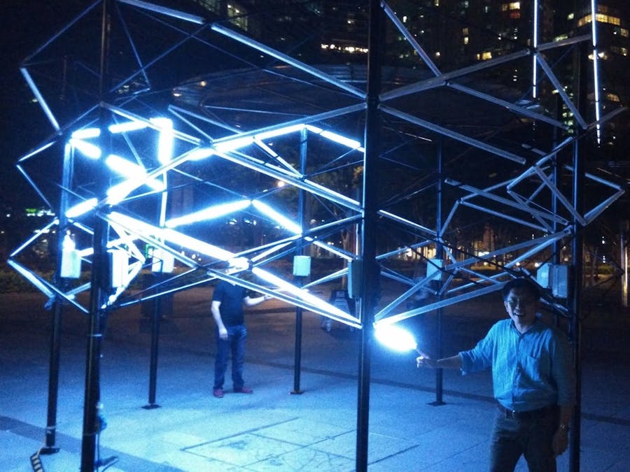
This light art installation was to cast a lightning bolt on a 3m tall by 6m wide structure populated with 1m white LED strips when the button was pressed.
After much testing, I decided to have eight Arduino Nano as passive I2C slaves just receiving commands from the I2C master and all my coding would be centralized in the I2C master. This makes controlling the code version easily and any changes does not need to re-flash all the eight I2C slaves. This was my first time writing my own communication protocols on top of I2C and I probably would exceed the maximum length of the I2C wiring distance.
Part 1 located at my blog at http://arduino-for-beginners.blogspot.com/2016/03/driving-bolt-at-ilightsmarinabay-using.html
MOSFET on breadboardThe next task was finding a way to drive the 1 meter 12V LED strips and we decided on using MOSFET for this purpose. This was my first time using MOSFET and lots of it, around 80 pieces of MOSFET to drive around 80 pieces of 1m LED strips.
Bolt PCB circuitOnce this test was done, the next step was making a custom PCB for this purpose as soldering 12 LED strips to 8 I2C slaves on a prefboard is not fun at all. With my very limited skills in EagleCAD, I started drawing up the schematic diagram and board drawing using 12 MOSFET driven by 12 pins on the Arduino Nano.
I usually take weeks and many many revisions to correct many errors before I make them into an actual PCB but this time around, time was not on my side and after 3 revisions within 2 days, I send to get the PCB done. Just in case the I2C does not work, I added a circuit to use nRF wireless options into the circuit as a backup plan. Always have backup plans.
Once the PCB was done, I work on the I2C coding by sending a coded message from the Master I2C to a slave I2C as follows, 20 to turn on 1st LED, 21 to turn on 2nd LED till number 32 to turn on the 12th LED as there was a possible of 12 LED per structure columns / segments. To turn off the LED, I send 40 to turn off 1st LED and 41 to turn off 2nd LED till 52 to turn off the 12th LED.
- Turn ON code: 20 to 32
- Turn OFF code: 40 to 52
The I2C slaves just listen to the above code and does a digitalWrite(pinNumber,HIGH) and digitalWrite(pinNumber,LOW) based on the corresponding numbers received.
Once this was working, I hook up ALL the eight I2C slaves to the I2C master in a bus with 4K7 pull-up resistors.
To ensure the I2C bus can take longer wires, I was using 2m of wires between each Nano running the I2C slave codes and it was still working. The drawback of this design is that if any of the Nano was down, it will pull down the I2C bus and the entire I2C bus will goes down. A proper design was to use a bi-directional high speed logic level shifter to buffer both sides of the bus from bringing down the I2C bus.
Here is the video of the model of bolt used for programming the lightning patterns.
Here is a video of #Bolt on display at iLightMarinaBay in Singapore with the Sands in the background.
Here is the #Bolt at a permanent location in APW Bangsar.


Comments
Please log in or sign up to comment.