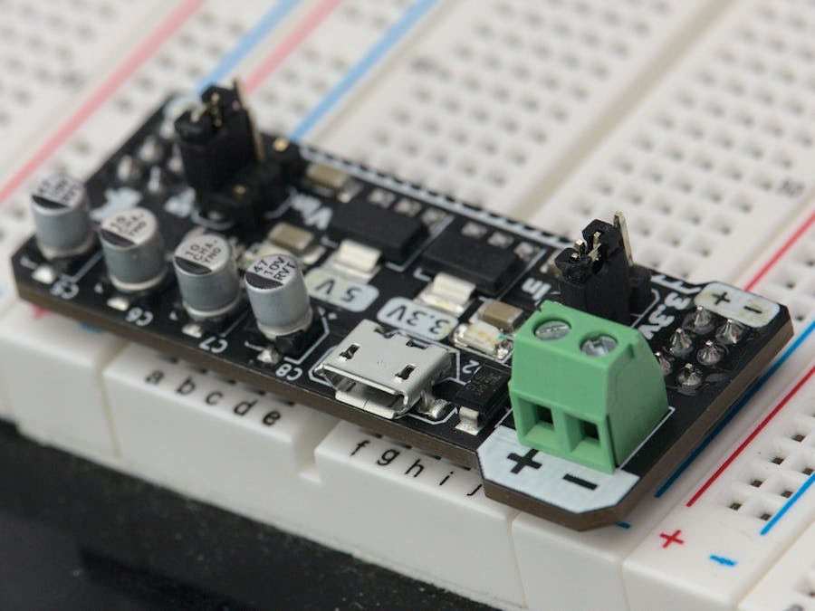
This is an open source hardware project, so be sure to check out the links below for even more info, and to buy your own!
- View Repo on Github
- Check out the Documentation Website (work in progress)
- Buy on Tindie!
- See more pictures!
While working with some of the more common breadboard power supplies that are available, I was always wanting something easier to use.It seems like these days I have significantly more Micro USB cables and USB wall adapters laying around than I do wall adapters with a barrel connector. There was also that female USB A port that I never found a good use for.
I liked the way it fits into the breadboard, and the 3.3V and 5V regulators are handy. However, I wanted something a bit more practical for my circuit experiments.
So what to do when faced with wanting something to exist that doesn't quite exist yet? Make it!
I set about thinking about what it was that I wanted to have as a feature list:
- Micro USB Connector
- Screw Terminal for bare wires
- 5V and 3.3V regulators for common digital circuits
- Bulk capacitance for power filtering
- Indication for each regulator
- Selectable output for each side of a breadboard's power rails
- PCB Headers spaced to match the width of a standard breadboard
With this feature set in hand, it was time to start capturing the schematic.
Capturing the SchematicTo begin, I started a new project in KiCad and set to work placing the symbols needed. There would be a few functional blocks, but the schematic would be a very reminiscent of the voltage regulation circuits seen around.
The power entry is handled by both a screw terminal and a Micro USB connector. A diode of appropriate ratings is used to help prevent any reverse polarity connections.
Most of the functionality of the circuit comes into play with the two linear voltage regulators. These offer a 20V maximum and 1 A current limit for each output. Note that the Micro USB's 5V rail will be on the same side as the output of the 5V regulator. This means that whatever is supplying the power to the Micro USB cable will be what is supplying the 5V rail. This was to make sure that there wasn't a voltage drop on the 5V output if a 5V source is being applied to the input of the voltage regulator.
For more filtering, these electrolytic capacitors are included for both the 5V and 3.3V power rails. These will help reduce any dips in voltage as sudden spikes in current will have a place to draw power from beyond just that of the linear regulators.
Here we can see the output connectors and the selector switch to set which voltage source is applied to either left or right side.
Now that the symbols are placed, and the netlist created, it's time to layout the board.
Designing A Custom PCBHere is where a lot of the design decisions are made that make this design practical and interesting.
For most of the passive components (resistors, diodes, and ceramic capacitors) I like to use 1206 Surface Mount Devices to find a good compromise with size and being able to hand solder the board without significant magnification.
Using common footprints for the electrolytic capacitors and voltage regulators will make swapping out parts easier. This means that if you find yourself replicating this design, you can substitute your preferred parts.
To get the best view of the board's layout, I recommend checking out the source files in KiCAD.
In order to make the board fit into the breadboard's power rails, the 2x3 PCB headers need to be spaced accordingly. This unfortunately isn't as standardized as one would like, but it seems like most are based off of 100 mils spacing.
Mixing in millimeters, the board size would end up dimensioned as below.
In order select which voltage source is put on the breadboard rails, a standard 2x3 PCB header is modified by removing two pins to create the desired shape. This allows jumpers to be used to connect the center pin to either of the three outer pins. This also makes it easier to not accidentally connect two voltage sources together.
I wanted to take the design even further and think about what happens after I've finished a breadboard experiment and want to transfer that into something more permanent. I thought about how cool it would be to combine this power supply with the prototyping boards that replicate breadboards with solder connections.
I simply copied and pasted the design into a new project, and added the breadboard rows and power connections to create the integrated version.
Be sure to check out the branch of the repository that has the integrated version's source files.
Integrated Micro Breadboard Power Supply
What's NextI've been working on this project for a few months, and have enjoyed creating both the artwork and the layout designs. I've ordered some extra PCBs and components and have made them available for purchase on Tindie.
I want to see if others have some feedback so I can incorporate some user experience into the next revision. Be sure to let me know what you think, I'd love to hear any feedback good or bad!
I still have some work to do on the documentation website, and might end up sharing some of the information seen on this project page.
I also need to try out some more circuit experiments with these boards, so be sure to comment if you have any suggestions for what you'd like to see!


Comments
Please log in or sign up to comment.