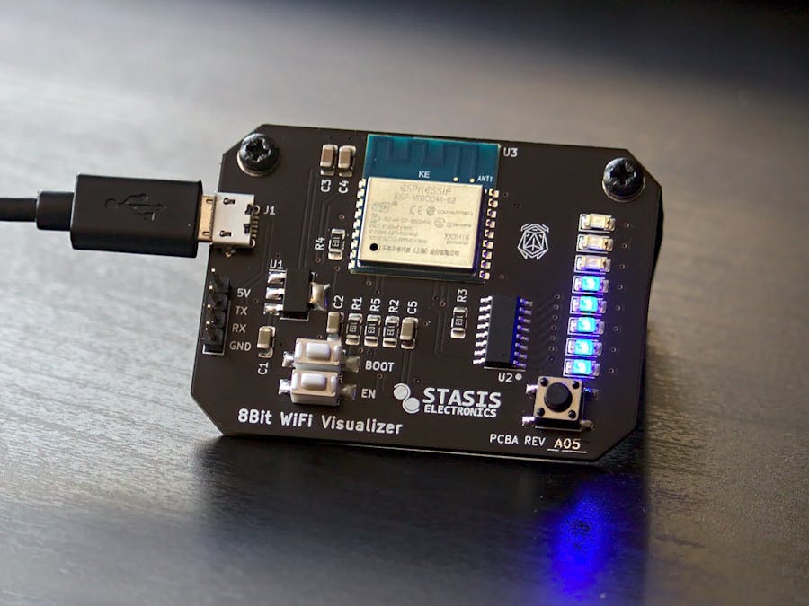
At its core, this board design is a simple desk toy that connects an ESP8266 module to a shift register to display data on the 8 blue LEDs. To make things a little bit more interesting, I've written an Arduino sketch that measures how many packets are flying around on the ESP's WiFi channel, and displaying the intensity on the LEDs much like a VU meter.
How does it work?The Arduino sketch uses the promiscuous mode of the ESP8266 to allow it to capture any packets present on the selected AP Channel. This means that the board can see all the activity on that channel without connecting to any of the networks itself.
These packets are like the envelopes of the internet activity: containing the data sent between devices and the internet. By counting how many packets the board sees in a given time interval, it can display the intensity of the network activity on the 8 LEDs using a shift register.
On Start UpWhen the board is first powered on, it will look around at all the networks that it can see. It will use their signal strength (RSSI) to find the strongest network and set the channel to that network's channel.
The 11 WiFi channels are slices of the frequency band that 2.4 GHz WiFi operates on. These slices allow different networks to separate themselves so they don't get in each other's way.
Changing The ChannelWhile the board is running, you can change the channel using the user button the lower right hand side of the board. Holding down until the LEDs start flashing the current channel in binary. Pressing the button will cycle through the 11 WiFi channels.
Hold the button again when you've selected the channel you want (usually the channel with your home network). The board will stop flashing the selected channel and go back to displaying the network traffic intensity.
Converting Packets Per Second to LEDsAs the board is counting up all the packets it sees fly by it's antenna, it is calculating a derivative. This is a change in number of packets in a set change in time. If there are 50 new packets since we last checked, and we check every 100 ms, then that can be converted to 500 Packets Per Second (ΔP/Δt) or 50 packets ÷ 0.1 seconds.
If we only have 8 LEDs to display our values, we need to scale the Packets Per Second rate to a number between 1 and 8. A design decision is made to always have at least one LED on even if there's no packets seen, so we can tell the board is powered.
A maximum rate is needed to figure out what constitutes all 8 LEDs being lit. Then we can do some math to figure out what our measured rate is proportional to that 8 LED maximum.
To make sure we always have whole numbers (integers), we can use a ceiling function to round up to the nearest whole number.
Now that we have the number of LEDs we want to turn on, we need to figure out what to send to the shift register. The Arduino function shiftOut() requires a byte of data (integer between 0 and 255). The value that we send will be such that for every 1 in the 8 bits, that LED will turn on. Taking advantage of some math, we can quickly go from number of LEDs to the correct binary number.
Wrapping it all up, we can now take this and put it in code:
byte n = pow(2,ceil((packets_per_second/max_rate)*8.0)) - 1;
digitalWrite(LATCH, LOW);
shiftOut(DATA, CLOCK, MSBFIRST, n);
digitalWrite(LATCH, HIGH);By keeping track of the greatest rate of packets the board has seen so far, we can automatically adjust the maximum value used to set the scale.
if(packets_per_second>max_rate){
      max_rate= packets_per_second;
    }
We can also have the max rate slowly decrease as it runs to adjust to periods of low activity.
if(packets_per_second>max_rate){
    max_rate= packets_per_second;
}
else if(max_rate>minimum_max_rate){
    max_rate -= max_rate*refresh_rate/500;
}By pressing the button once while the board is in normal operation, we can reset the scale back to a default value.
What still needs work?The design is mostly finished, and I am now working on the documentation. I have built a website dedicated to this project's documentation using Github Pages, and Jekyl (a static site generator).
I also need to make some more media to show off how it works!
Can it do something else?Yes! The board is designed in KiCAD and the firmware written in Arduino. All the source files are included in the Github repository. The design is open source, and you are free to replicate and modify the design!
Want to make your own?Parts kits are available on Tindie, with assembled boards available too!
Want to learn more?


_4YUDWziWQ8.png?auto=compress%2Cformat&w=48&h=48&fit=fill&bg=ffffff)


_Ujn5WoVOOu.png?auto=compress%2Cformat&w=40&h=40&fit=fillmax&bg=fff&dpr=2)
Comments