

Hardware components | ||||||
 |
| × | 1 | |||
Estimated Time: 2-4 hours
Estimated Total Cost: $75 ($130 if you buy the full Grove Kit)
Introduction:
This is my first time using MediaTek's LinkIt ONE, along with Seeedstudio's
Grove Starter kit.
These two items comprise a very impressive easy-to-use development kit that is perfect for either creating proof-of-concept wireless products, or creating “one off” or low volume custom solutions requiring a microcontroller and wireless connectivity.
My goal was to create an entry alarm for a house under construction that would notify me when visitors, either expected (such as contractors) or not, arrived. WIFI wasn't an option, so this kit with its GSM radio and SMS libraries looked like an ideal solution.
Amazingly in a couple of hours I had created a door open sensor that sends my phone an SMS every time the door is opened. It does this using a light sensor and detecting the interruption/breaking of a beam of light across the open door. Additionally, a buzzer will beep continuously until the door is closed and the beam of light is reinstated.
For those interested, I've described the LinkIt ONE kit contents in depth below.
For more in depth information, you probably want to read through the provided developer’s guide first. MediaTek’s website also has complete and detailed tutorials on their hardware, and how to run a sketch.
Skip to "Step 1" If you'd rather just create the project.
Kit Contents – LinkIt ONE:
For wireless connectivity, the LinkIt ONE board is a very
versatile one-size-fits all solution that includes a GSM radio with SMS and
GPRS data connectivity, 802.11 b/g/n Wi-Fi, basic rate (BR) and enhanced data
rate (EDR) Bluetooth, Bluetooth Low Energy (BLE), and a GPS receiver.
Just as important as the radios themselves, the board comes with the necessary software to easily use the radios. The software and APIs are nicely incorporated into and accessible from an Arduino development environment.
The LinkIt ONE leverages an ARM7 core at 260MHz with 16MB flash and 4MB ram (of which approx. 2MB is available for user application). Also included on the board is a card holder that can either work as an SD card slot or to retain a GSM SIM card for GSM/GPRS connectivity (850/900/1800/1900 MHz). Since the SD card consumes the SPI port, you will be able to use either the SD card or the SPI port (there is a configuration switch), but not both simultaneously.
The board has 3 analog pin inputs, I/O pins that can source/sink 1mA of current, and a UART. The micro USB connector is used to power and program the board.
This project uses the SMS module for communication. Once the opened door is detected, a canned SMS is sent to a pre-programmed phone number.
The quickest way to get this board running is to install the LinkIt SDK onto a previously installed Arduino IDE.
The LinkIt SDK is advertised to be compatible with version 1.5.6-r2 BETA and 1.5.7 BETA. You can find these older Arduino releases here.
Within the Arduino model of programming, you create “sketch” that consists of (a) an initialization function (setup) and (b) a main loop (control logic). The initialization function is used to setup and initialize I/O pins and the various communication modules such as WiFi. The main loop is where your controller’s logic is written; it is where it continuously checks for events (polling) and responds to them.
Under the covers, the LinkIt ONE board is running multiple concurrent tasks to keep all of the communication modules operating. The simplified Arduino programming model, though, reduces the user program to a single threaded continuously operating infinite super-loop.
Step Two: Download and Install the LinkIt ONE SDK
Download and install the LinkIt ONE SDK from here. The LinkIt SDK installs “into” the Arduino environment/IDE to provide direct programming access.
If the Arduino IDE has been previously launched the SDK installer should be able to find it and put itself in the correct location. You will want to ensure the destination location is correct (the same as the Arduino IDE) and fix it if not.
During this process, make sure you allow the MediaTek USB Driver to be installed.
If your device manager (under ports) shows a driver problem after the driver is installed and the board is plugged in, right click on the device and “update driver software” and “browse my computer for driver software”. Then navigate to the install directory and hit “next”.
If the 2 new ports don’t show up at all and you are running Windows 7 or 8, you may have to disable driver signing check first.
Step Three: Set up the LinkIt ONE
For this project, configure the board’s slider switches in the following manner:
The “ms/uart” switch should be in the “uart” position. This allows the board to be programmed by the Arduino IDE.
The “USB/BAT” switch should be in the “USB” position to allow it to be powered by a USB cable.
The “SPI/SD” should be in the “SPI” position.
Step Four: Configure the Arduino IDE to use the LinkIt Development Board
Go to “Tools”->”Board”-> and then select “LinkIt ONE”
Configure the correct communication port by referring to the device manager. If the drivers are installed correctly and the board is connected, there should be 2 devices under ports that are named “MTK USB Debug Port” and “MTK USB Modem Port”
In the example above, the port number is “com 23”. With this information, configure the Arduino IDE to use via the menu option “Tools”->”Port”->”COM23”.
Step Five: Make sure everything is working correctly by running the provided “Blink” example.
The Blink example will make one of the tiny LEDs mounted on the LinkIt ONE board slowly flash on and off (It will be hard to see if the Grove Starter Kit cape is already plugged in).
Do this by using the menu option “File”->”Examples”->”01.Basics”->”Blink”
Then, use the IDE to upload and execute the program, “File”->”Upload”
The LED should hopefully be blinking!
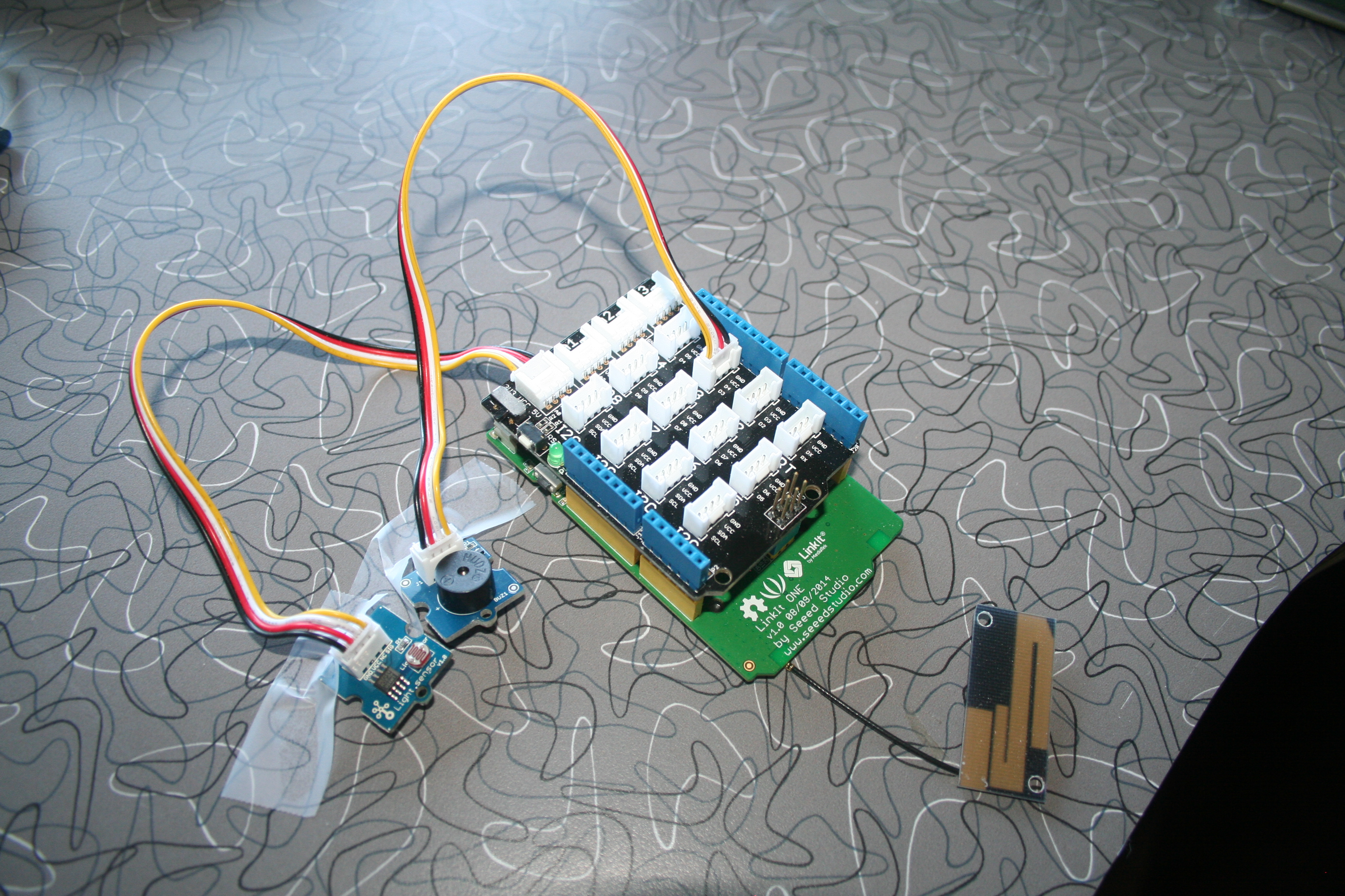
Step Six: Plug in the Grove Sensors
Besides 12 sensors and output devices, this Grove Kit also includes
an Arduino ‘cape’ that plugs into the LinkIt board. The cape is simply an adapter between the
Arduino header sockets and 4 pin connectors, where each 4 pin connector is
assigned a digital I/O pin or analog pin. From there you can use the included 4-pin cable assemblies to easily plug in the various sensors.
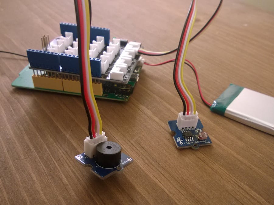
This project uses the light sensor and the buzzer components. To detect the open door, the light sensor will detect a change in light intensity when the light beam is broken by the opened door. The buzzer is used for local audible feedback and testing by providing a beeping noise as long as the controller thinks the door is open.
Connect the buzzer to the “D3” pin header, and the light sensor to the “A0” analog input pin header.
Step Seven: Plug in the GSM Antenna and SIM card
The next step is to attach the GSM antenna to the board
Lastly, you will have to flip the board over and insert an active SIM card for a GSM network. Since I am using T-Mobile as my carrier, it was pretty easy to temporarily steal the wife’s SIM card from her phone for testing. For actual usage, I would purchase a prepaid “pay-as-you-go” plan that would simply charge me on an SMS by SMS basis.
Note that the SIM card and SD card holders are stacked on top of each other. If your board came with a micro SD card already inserted, it's fine to leave it in the slot. Because the slider is switched to SPI, the SD card can't be used. Although the holder is for a full-size SIM card, you can use a mini-SIM card if you carefully line up the contacts and insert the card in the correct orientation.
Note that the notch of the smaller SIM card is oriented towards the opening, while the square corners are pushed in first and to the back.
Step Eight: Use print statements and a serial terminal
To program and debug easily, one of the most effective methods is to use print statements to show program execution and progress. On this board, it is made pretty easily by using the ‘MTK USB Modem Port’ device as an output terminal and sending characters to it through the Arduino ‘Serial.print’ function.
My windows serial terminal of choice is PuTTY (if you're using Mac or Linux, try CoolTerm). To configure this software, you would do something similar to the following:
Just make sure that you substitute the correct com port number. This, again, is visible through the device manager as a device named ‘MTK USB Modem Port’.
One inconvenient thing here to note with windows: you must open the port up AFTER the board has been booted. And if you have an open port up, you will want to shut it down BEFORE rebooting the board. Otherwise, windows will refuse to communicate with it.
This is important trivia because after an Arduino program upload, the board is always rebooted before execution begins. So if your serial terminal window remains open, you will lose communication.
Step Nine: The Code
Now with everything in place, it is time to write the control code. The code provided at the end of this article is the complete code I used for this project. It was created by rapidly combining the provided examples of blinking the main board’s led, using the buzzer, using the light sensor, and sending an SMS.
One important parameter that will need to be changed is the “threshold” (line 19 in LinkItDoor.ino).
After the value of the light sensor is read, its value is compared against the threshold. If the value is *lower* than the threshold, the alarm is triggered. The value of the threshold will need to be set high enough to filter out ambient light. Similarly, the light source/beam on the other side of the door opening has to have enough intensity to keep the alarm from triggering.
Next steps in the project
With a little bit more code, a whole bunch of features is possible. On my wish list are the following ideas:
- Include a time-stamp in the outgoing SMS message
- Incorporate a temperature sensor, and include its value in outgoing SMSs.
- Incorporate an SMS responder, capable of receiving SMS messages, parsing them for commands, and responding to the sender. This could be used for remotely turning on and off the sensor, along with finding out the house’s temperature.
- Include an incoming SMS filter based on sender’s phone number that will remove all incoming commands except those generated by my personal phone.
- Incorporate a BLE responder that can detect my phone in the vicinity and automatically turn off or temporarily disable the alarm function and keep SMSs from being sent.


Comments