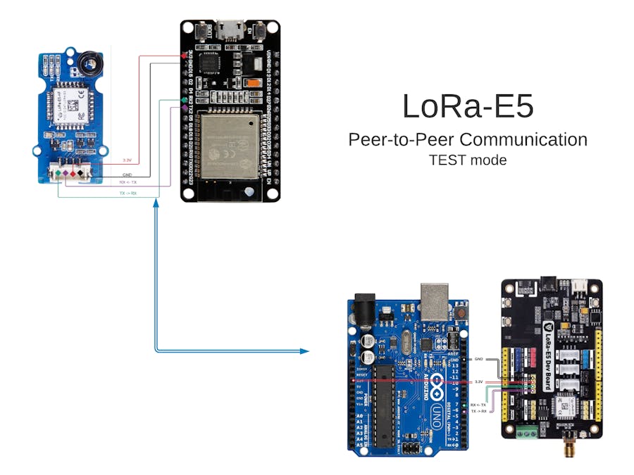
I started this project with the goal of exchanging messages between devices using LoRa-E5 without the need to have a LoRaWAN (and thus a LoRaWAN gateway). My primary source of information while developing this project was Seeed's official webpage on LoRa-E5 and the AT Command Specification document.
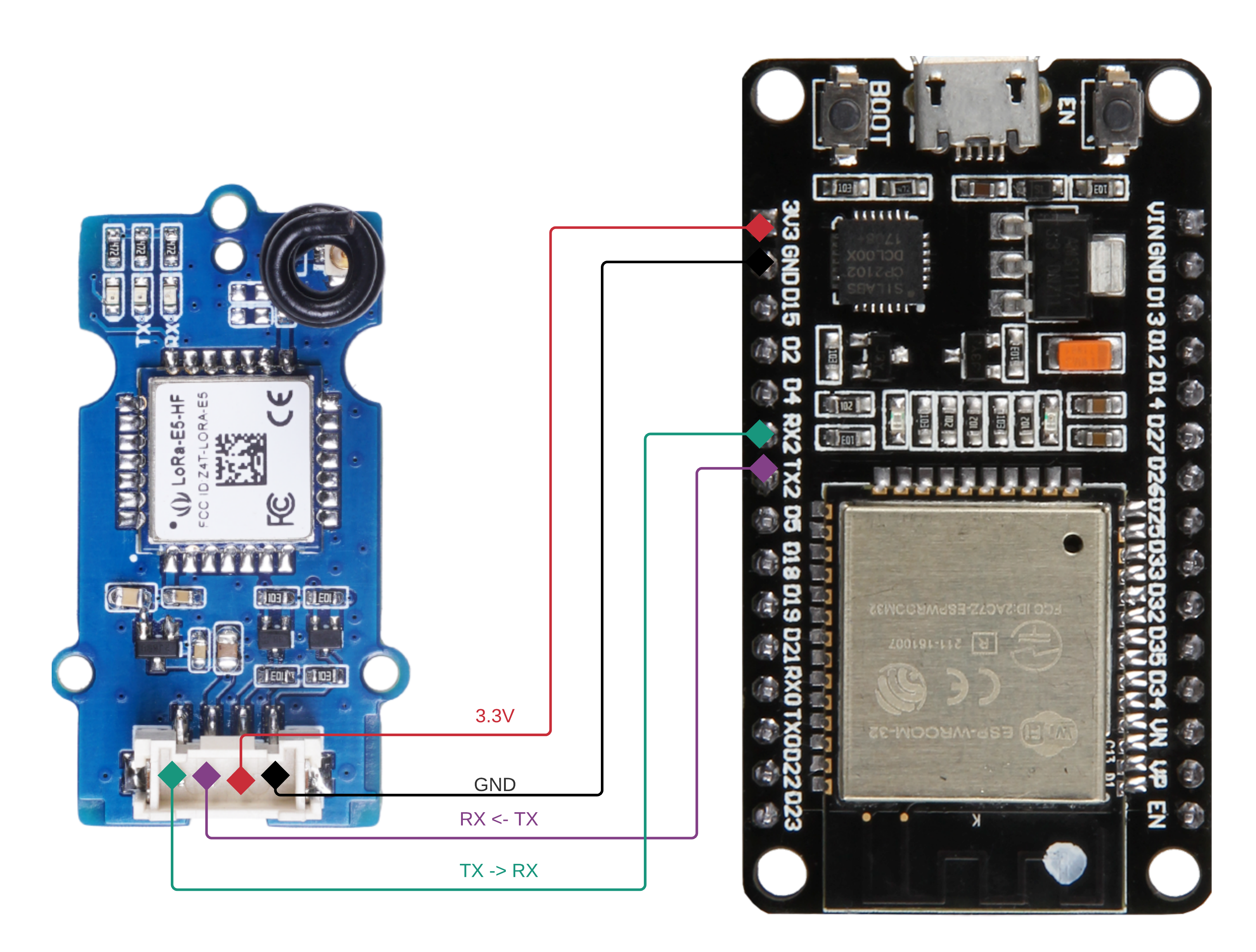
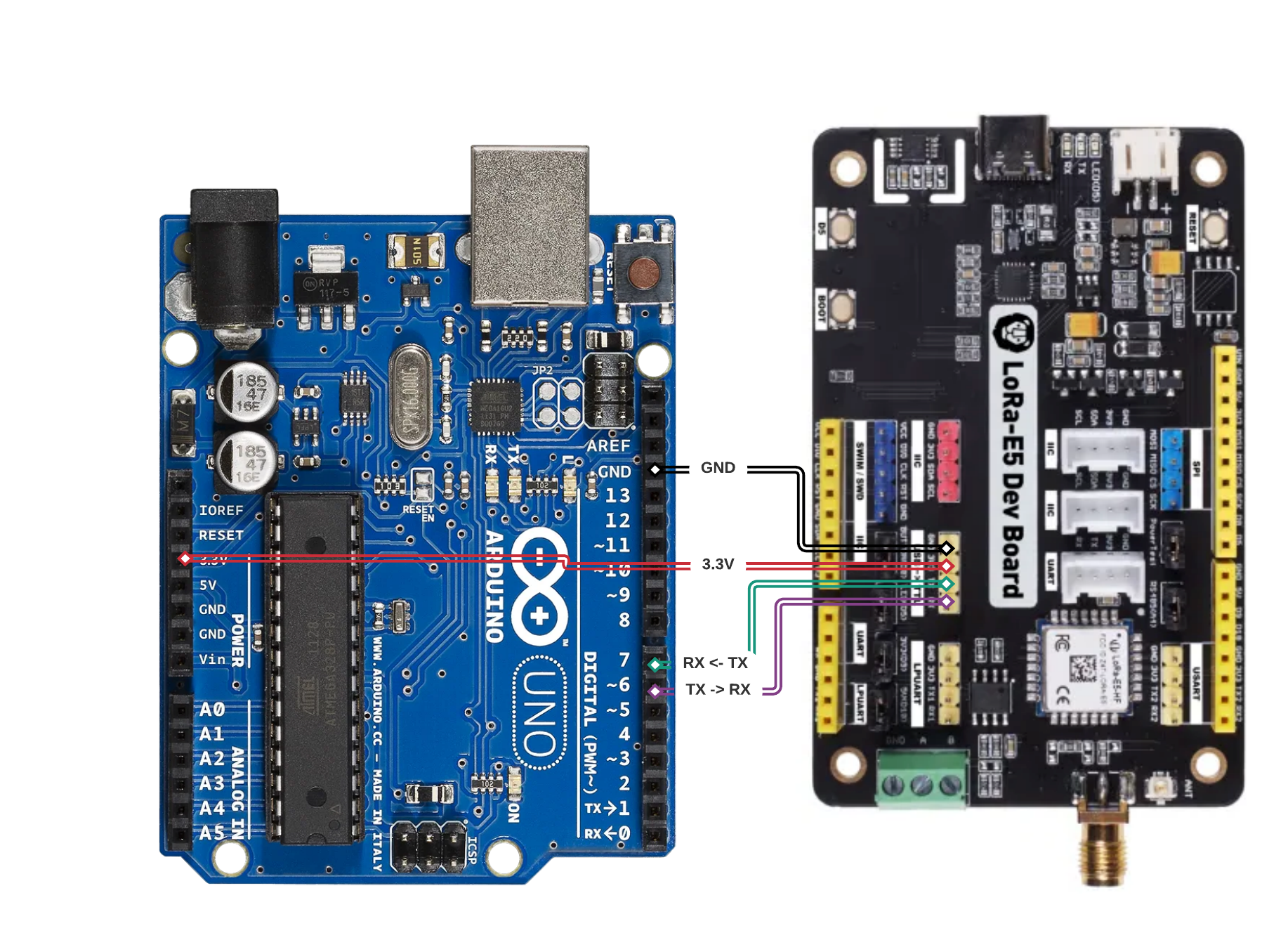
The LoRa-E5 module has an embedded MCU in addition to the LoRa modem, however I am more comfortable using my own choice of microcontroller (Arduino / ESP) device that I can program using Arduino IDE. So I decided to use the LoRa-E5 just as a LoRa modem, one with my ESP32 Dev Module and another with an Arduino Uno.
In this project, I use
- Arduino Uno + LoRa E5 Dev Module as a Transmitter
- ESP32 Dev Module + Grove LoRa E5 as a Receiver
You may choose to have your transmitter / receiver with any choice of UART supporting microcontroller in combination with any LoRa-E5 modules
Since I'm using the LoRa modules only as the LoRa modems to which I shall communicate through AT commands, I decided to tryout sending just the AT commands and getting their response. Thus I programmed my microcontroller boards with a Serial passthrough program.
For the Arduino Uno board, here is the program I used
#include<SoftwareSerial.h>

SoftwareSerial e5(7, 6); // (RX, TX)

void setup() {
  // put your setup code here, to run once:
  Serial.begin(9600);
  e5.begin(9600);
}

void loop() {
      while (Serial.available() > 0) {
        e5.write(Serial.read());
    }

    while (e5.available() > 0) {
        Serial.write(e5.read());
    }
}
and for the ESP32 board, here is the program I used
void setup() {
  Serial.begin(9600);
  Serial2.begin(9600);
}

void loop() {
    while (Serial.available() > 0) {
        Serial2.write(Serial.read());
    }

    while (Serial2.available() > 0) {
        Serial.write(Serial2.read());
    }
}
Once the programs were uploaded successfully, I opened up two Cool Term windows (you may choose Arduino IDE's Serial Monitor but you can open only one Serial Monitor at a time), set the respective COM ports with baud rate as 9600 as connected to them.
My first command to both of them was just sending 'AT' and voila, here is the response
Now that my devices are successfully doing serial passthrough and are responding to my AT commands, it's time to set the devices in TEST mode so they can communicate with each other without needing a LoRaWAN gateway
First I setup the receiver terminal (ESP32 + GroveLoRaE5) so I have the messages when the transmitter sends them, thus I send the following commands
- AT+MODE=TEST
- AT+TEST=RXLRPKT
On the Transmitter terminal (Arduino Uno + LoRaE5DevModule), I send the following commands
- AT+MODE=TEST
- AT+TEST=TXLRPKT, "AB"
- AT+TEST=TXLRSTR, "AB"
Here is the response from the devices
Note that the LoRa-E5 can receive the messages only in HEX format whereas it can transmit in both HEX as well as STRING format. This is why you see 2 different messages received "AB" and "4142" inspite the transmitted messages in both the case was "AB" (but as HEX in the first instance and as STRING in the second).
For more info on what can you do in the TEST mode, please refer to the AT Command Specification document.
While I was writing this project, I wondered if I can put a LoRa module on TEST receive mode (by sending AT+TEST=RXLRPKT), then send from that same module to check if it receives the packets by itself (by sending AT+TEST=TXLRPKT, "AB"). It turns out that the TEST receive mode goes off the moment I transmit something from it. So I cannot use a LoRa modem in both TEST receive as well as TEST transmit at the same time.Exchanging messages with an Arduino program
Let's now program the Arduino / ESP32 to transmit and receive messages programmatically.
Instead of writing code from scratch, I came across one of official LoRa guides by Seeed Studio where an Arduino code to communicate with LoRa E5 is provided. It is developed for a different hardware so with a number of tweaks, I have been able to make it work for the devices used in this project
Transmitter Code - Arduino Uno
#include <ArduinoJson.h>
#include<SoftwareSerial.h>

SoftwareSerial e5(7, 6);

static char recv_buf[512];
static int led = 13;
int counter = 0;
static int at_send_check_response(char *p_ack, int timeout_ms, char *p_cmd, ...)
{
    int ch;
    int num = 0;
    int index = 0;
    int startMillis = 0;
    va_list args;
    memset(recv_buf, 0, sizeof(recv_buf));
    va_start(args, p_cmd);
    e5.print(p_cmd);
    Serial.print(p_cmd);
    va_end(args);
    delay(200);
    startMillis = millis();

    if (p_ack == NULL)
        return 0;

    do
    {
        while (e5.available() > 0)
        {
            ch = e5.read();
            recv_buf[index++] = ch;
            Serial.print((char)ch);
            delay(2);
        }

        if (strstr(recv_buf, p_ack) != NULL)
            return 1;

    } while (millis() - startMillis < timeout_ms);
    Serial.println();
    return 0;
}

void setup(void)
{
    Serial.begin(9600);
    pinMode(led, OUTPUT);
    digitalWrite(led, LOW);

    e5.begin(9600);
    Serial.print("E5 LOCAL TEST\r\n");
    at_send_check_response("+AT: OK", 100, "AT\r\n");
    at_send_check_response("+MODE: TEST", 1000, "AT+MODE=TEST\r\n");
    delay(200);
    digitalWrite(led, HIGH);
}

void loop(void)
{
      char cmd[128];
      counter=counter+1;

      // Transmit HEX Value
      sprintf(cmd, "AT+TEST=TXLRPKT,\"%d\"\r\n", counter);
      int ret = at_send_check_response("+TEST: TXLRPKT", 5000, cmd);

      if (ret)
        Serial.println("Sent");
      else
        Serial.println("Send failed!\r\n\r\n");
      delay(5000);

}
In this program, only an integer from the counter variable is sent once in every 5 seconds. However, you may fetch a sensor value or build a JSON character array and transmit it using the HEX mode or STRING mode respectively.
Receiver Code - ESP32
#include <ArduinoJson.h>

static char recv_buf[512];
static int led = 2;

static int at_send_check_response(char *p_ack, int timeout_ms, char *p_cmd, ...)
{
    int ch;
    int num = 0;
    int index = 0;
    int startMillis = 0;
    va_list args;
    memset(recv_buf, 0, sizeof(recv_buf));
    va_start(args, p_cmd);
    Serial2.print(p_cmd);
    Serial.print(p_cmd);
    va_end(args);
    delay(200);
    startMillis = millis();

    if (p_ack == NULL)
        return 0;

    do
    {
        while (Serial2.available() > 0)
        {
            ch = Serial2.read();
            recv_buf[index++] = ch;
            Serial.print((char)ch);
            delay(2);
        }

        if (strstr(recv_buf, p_ack) != NULL)
            return 1;

    } while (millis() - startMillis < timeout_ms);
    Serial.println();
    return 0;
}

static void recv_prase(char *p_msg)
{
    if (p_msg == NULL)
    {
      Serial.println("Received null");
        return;
    }
    char *p_start = NULL;
    char data[128];       // To hold the received bytes as characters

    int bytes_len=0;
    p_start = strstr(p_msg, "RX");
    if (p_start && (1 == sscanf(p_start, "RX \"%s\"", &data)))
    {
      for (int i=0; i<sizeof(data); i++) {
          if(int(data[i+1])==0) {
            bytes_len = i;
            break;
          }
    }

    // Convert the characters to a byteArray
      int message_len = bytes_len/2+1;
      byte out[message_len];
      auto getNum = [](char c){ return c > '9' ? c - 'A' + 10 : c - '0'; };
      for (int x=0, y=0; x<bytes_len; ++x, ++y)
        out[y] = (getNum(data[x++]) << 4) + getNum(data[x]);
      out[message_len] = '\0';

      // Print the received bytes
      for (int i=0; i<sizeof(out)-1; i++)
      {
        Serial.print(out[i], HEX);
        Serial.print("-");
      }
      Serial.println();
    }
}

void setup(void)
{
    Serial.begin(9600);
    pinMode(led, OUTPUT);
    digitalWrite(led, LOW);
    Serial2.begin(9600);
    Serial.print("Serial2 LOCAL TEST\r\n");
    at_send_check_response("+AT: OK", 100, "AT\r\n");
    at_send_check_response("+MODE: TEST", 1000, "AT+MODE=TEST\r\n");
    at_send_check_response("+TEST: RXLRPKT", 5000, "AT+TEST=RXLRPKT\r\n");
    delay(200);
    digitalWrite(led, HIGH);
}

void loop(void)
{
      char cmd[128];
      // Transmit HEX Value
      sprintf(cmd, "");
      int ret = at_send_check_response("+TEST: RX", 1000, "");
      if (ret)
        recv_prase(recv_buf);
      else
        Serial.println("Receive failed!\r\n\r\n");
      delay(5000);

}
In this program, since all the receiving bytes are read from the serial port as characters, they are converted back to bytes in the recv_prase() function and printed out on the Serial port. You may use these values in the out variable to perform any comparison and take action (liked turning on/off an led or a relay) or pass those bytes to another peripheral, etc.
Here is the output of my Serial terminals demonstrating the transmission and reception
I hope this helps in getting started with LoRa-E5 for you!
I'm working on another project that sends the data packets to The Things Network. If you are interested in exploring that, please check it out here


_ztBMuBhMHo.jpg?auto=compress%2Cformat&w=48&h=48&fit=fill&bg=ffffff)


Comments
Please log in or sign up to comment.