


Hardware components | ||||||
 |
| × | 1 | |||
| × | 1 | ||||
| × | 1 | ||||
Software apps and online services | ||||||
 |
| |||||
 |
| |||||
| ||||||
Hand tools and fabrication machines | ||||||
 |
| |||||
| ||||||
I have at disposal several drones, built from scratch by other students. I wanted to make it possible to find the drone’s position in real-time, so later on I can use this project to make an autonomous drone, which can go to locations given by me.
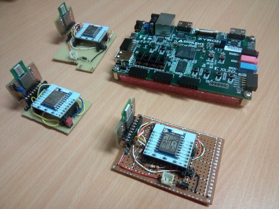
Making the hardwareThis is how the ESP8266 and the DWM1000 are connected.
I provided with a PCB, which you can use. Here are the gerber files, so you can use whichever PCB designer program you are accustomed to.
You can either create your own PCB or use a breadboard for testing purposes like I did.
First you have to set up the ESP8266 library in order to use it.
Go to: File->Preferences->Settings
At the Additional Boards Manager URLs, type the following:
http://arduino.esp8266.com/versions/2.4.1/package_esp8266com_index.json
Then go to: Sketch->Include Library->Manage Libraries
Type at the Filter section: ESP8266 and look for ESP8266 Built-In by Simon Peter
Create 2 new folders. 1 for tag and 1 for anchor. Copy everything from src to both of the folders. Now copy the Anchor.ino to the Anchor folder, and the Tag one respectively. In order to install it to the board you need the following settings.
First set the number of anchors to the amount that you are going to use. The recommended amount of anchors to use are 4, but you can use more or less.
NOTE: Don’t forget to change the number of anchors at the tag as well. This application is ready only for a one tag use.
Then, you have to “name” your anchors, before you can upload them. You can assign numbers to DEVICE_ADDRESS, which should be assigned in order, starting with one.
Board settings -> Tools:
- Board: Generic ESP8266 module
- Flash mode: DIO
- Flash size: 512K (64K SPIFFS)
- Debug port: Disabled
- Debug Level : None
- IwIP Variant: v2 Lower Memory
- Reset Method: ck
- Crystal Frequency: 26MHz
- Flash Frequency: 40MHz
- CPU Frequency: 80MHz
- Builtin Led: 2
- Upload Speed: 115200
- Erase Flash: Only Sketch
- Port: Specific
- Programmer: AVRISP mkll
NOTE: Some of them might change, look after your ESP8266 version details, before you proceed.
In order to connect the ESP to the PC, you'll need an UART cable. Connect the following cables:
- Yellow -> TXD
- Orange -> RXD
- Red -> VCC
- Black -> Ground
NOTE: When you are uploading the code, make sure, that you put a jumper to the JMP1, GND pins. Only by this can you upload the code. After the program is uploaded, remove it, and now it is safe to remove it from the computer, otherwise it may reset itself while disconnecting from the computer. Anyway, when you want to use these modules, you'll need to remove the jumper before powering it on.
Now you need a 3.3V power supply to power the anchor. If you have a diode inserted, then you'll need 3.7-3.9V, depending on the voltage drop. Find a place where you want to make your measurements, and put these down. Don’t power it just yet. Connect the tag to your computer, and then open the program you want to use to monitor the serial port. After this you can measure the real distances.
NOTE: You can use alternative monitoring programs like Putty, Serial Port Monitor, Advanced Serial Port Monitor, etc.
Now, power on the anchors, and connect the tag to the computer. Use the Arduino built-in monitor to get the necessary data. Leave it for few minutes to have some results, and then power off the anchors. Save your data to file called Measurement.txt, open it with a text editor and replace the ‘.’ to ‘,’.
Now use the Data_organizer program to organize the data, and create the necessary code for it. Then you will have Measurement.m file.
After this, use Matlab to run the generated code. With it you can analyze your measurements, and find the average offset for each anchor.
Testing the triangulation methodThe part, where the tag is connected to FPGA is missing, because I’m currently working on the triangulation methods implementation, trying to minimize the resources it needs for the calculation, searching for the necessary inputs and outputs and testing it using hardware co-simulation. After I am done with it, then I will make the interface for it.
Simulink Hardware Co-Simulation
In its current state you can use my hardware co-simulation project to see how it works and test it with different inputs and outputs. There are two options. One for testing only the triangulation using the FPGA, and one, which doesn't require it. If you want you don’t want to use the FPGA, then use this one: pozi_2_2015a. When the project is opened, open the Vivado HLS block. Find the folder called Triang and select it.
NOTE: It might not work. The source of the problem is yet unknown, currently testing on different computers, Matlab, and Vivado HLS versions as well. For now it seems that the Vivado HLS 2017.4 and Matlab r2017a or b versions are the best choice.
After you started the project simulation, set the reset switch to 1, then both the Reset and the Start to 0. After this, just switch the Start to 1, and you can use different values, sources to see the results. When opening the scope, you can see the FPGA's inner states, whether it is waiting for the start signal, calculating the results or signaling the end of it.
If you plan on using the other method, using the FPGA, after opening the Pozi_3_Hardware_MCLK_2015b project, select the hwcosim block. Open the module, and browse the bit file.
NOTE: At the Model Configuration Parameters, at the Solver options choose the following settings:
- Type: Fixed-step
- Solver: Discrete
After I'm done with the optimisation, I'll have to implement the Kalman filter and the SPI interface. I could use SPI interface between the FPGA and the microcontroller, but I decided not to, because this makes testing significantly easier without requiring data in real time.


Comments
Please log in or sign up to comment.