Water and fertilizer are extensively used in modern agriculture. They are an effective and economical way to enhance yield quality and quantity, thus ensuring food security for the ever-growing population around the globe. However excessive use of fertilizers damages the plants and reduces soil fertility. Long-term use of fertilizer reduces the microbial activity and disturbs the pH of the soil. Diverse pesticides and excessive use of fertilizers directly or indirectly pollute air, water, soil, and the overall ecosystem which cause serious health hazard for living beings. A report from the Intergovernmental Panel on Climate Change finds that about 30% of global emissions leading to climate change are attributable to agricultural activities, including pesticide and chemical fertilizers use. Excessive use of water to produce crops causes the water level of the ground to go deep down as a result shortage of pure drinking water is a big threat to us. To grow 1kg of paddy requires 2500 liters of water, but farmers of Bangladesh are using 3300 liters of water to produce 1kg of paddy which means 800 liters are just wasted. In India, the numbers are much higher, almost 5500 liters.
We all know that we just can’t stop using fertilizer and groundwater to save the environment because that will lead us to less production of crops and will create a threat to the food security of the world. But these heavy numbers really influenced us to find a solution to reduce this pollution at a minimum rate which will be much more eco-friendly and will also increase the production rate a lot. Farmio is the solution to this.
Farmio is an autonomous and intelligent robot that will allow the farmers to measure important soil parameters like soil moisture, temperature, electrical conductivity, NPK, and pH and automatically apply the right amount of nutrients in the soil based on the measured parameters and plant type. It also stores the soil parameters of every point of the field for further analysis.
Farmio facilitates accurate nutrient management, which helps to sustain the ecosystem. Farmers can reduce the danger of over-application and consequent environmental pollution by applying fertilizers and soil amendments in the right proportions by precisely measuring the levels of soil nutrients. This focused strategy promotes ecologically friendly farming methods, reduces chemical runoff, and conserves natural resources.
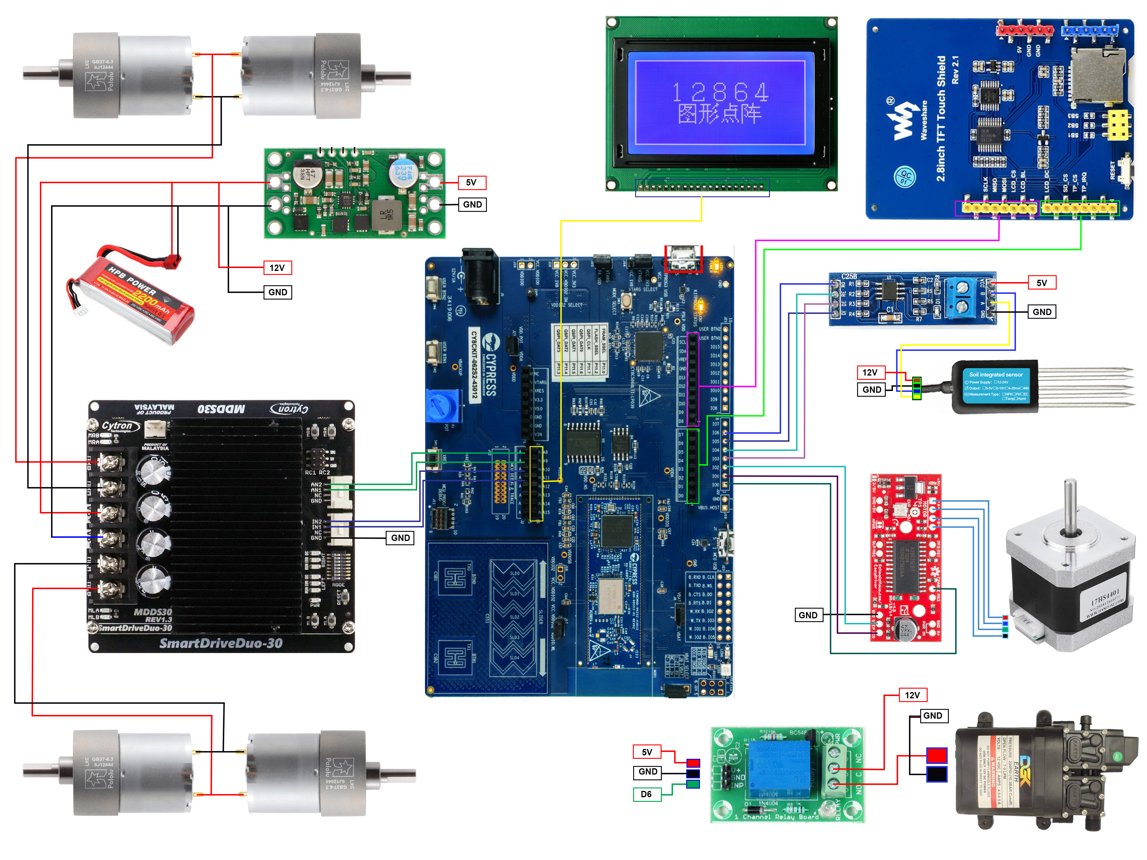
Farmio Hardware DesignThe main part of the Farmio autonomous robot is PSoC™ 62S2 Wi-Fi BT Pioneer Kit. For driving the robot I used 4 high power DC gear motors. For controlling the motors I used a Cytron 30A dual-channel motor driver. The driver can be controlled by two PWM and two digital pins of PSoC board. The driver is directly powered from 3 Cells Lipo battery. Some components of the robot required 5V
and for getting 5V I am using a Pololu 5V buck converter that converts 12 V to 5V. In my robot, I am using two displays. One TFT display is used to draw the track of the robot which track will be followed by the robot to take the soil reading and apply fertilizer. The track will be drawn in the display by touch input. The TFT display shield I used here is Arduino header compatible. I used a Grove base shield for Arduino to attach the TFT shield to the PSoC board.
Track distances can be adjusted by the Capsense button and slider. The robot will follow the track drawn on the TFT and read the data from all crossing points on the line.
I am using another graphics display to show important messages and measured soil parameters. The display is a 128X64 graphics display with an ST7920 serial driver. A short demo video is attache below.
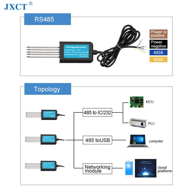
For reading the soil parameter I used a 7in1 soil sensor that can measure soil moisture, temperature, conductivity, pH, nitrogen, phosphorus, and potassium. The sensor supports the Standard Modbus-RTU protocol with a default baud rate of 9600. I used a MAX485 module, a low-power transceiver for TTL to RS485 communication to connect the sensor with the PSoC board.
For measuring the soil parameters, the sensor leads need to enter inside the soil. I made a vertical lifting mechanism using a stepper motor for vertically moving the sensor.
Testing of the mechanism:
After measuring the soil parameters the Farmio robot automatically applies the right amount of liquid fertilizer by spraying on the soil through a high-pressure pump and mist nozzle. For controlling the 12V pump with the digital pin of PSoC board I used a relay module here.
Assembling:Motor Connection:
Four high-power gear motor is placed on a plywood board. The board size is 1.25 feet X 1.75 feet.
The following picture shows the motor connection with the Cytron motor driver.
The PSoC Board and the Breadboard placement on the robot base.
The following image shows the 7in1 soil sensor placement on the vertical moving plate.
The soil sensor will be moved by a steeper motor. The following image shows the motor driver connection with the motor and the PSoC board.
After fixing the sensor mechanism with the base of the robot the robot looks like the following image.
The liquid fertilizer container is placed behind the sensor unit. The fertilizer will be sprayed into the soil through the high-pressure 12V DC pump that is placed with the fertilizer container. A mist nozzle is connected to the outlet of the pump. See the photo below.
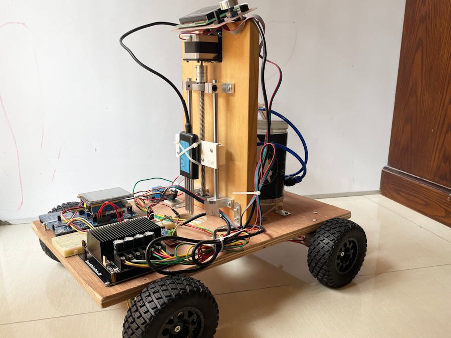
After assembling all the parts and display the Farmio robot looks like the following photo.
Another photo of the Farmio.
The following short video demonstrates the soil sensor movement towards the soil. The metal leads of the sensor enters into the soil by the pressure of the stepper motor. It waits 5 seconds to reads the soil parameters and pull-out the sensor again to its initial position.
The video is coming soon...For the time limitation I could not record the video. Soon, I will publish the video of the full and practical operation of the Farmio with more details.
Operational Flow-ChartThe following diagram shows the work flow of the robot.
Developing Firmware
For developing the firmware I used ModusToolbox with Eclipse IDE. I found ModusToolbox very convenient for the firmware development of PSoC devices.
At the very beginning, I created a new empty application on Modustoolbox using Project Creator as shown in the following screenshot.
I gave the name "Farmio" for my project.
The project required lots of complex tasks. So, I decided to use Freertos OS for my project. Before doing anything I included freertos Core to my empty application from the Library Manager as shown in the screenshot below.
After adding the library I updated the project as shown in the image below and the freertos library was successfully added to my project.
Just adding the library is not enough for the successful working of the freertos. You need to add FreeRTOSConfig.h file with the main source. So, I added the freertos configuration file to my project as shown in the screenshot below.
For successful compilation, I added "FREERTOS RTOS_AWARE" to the component of the advanced configuration section of the Makefile as shown in the image below.
To make sure everything was working perfectly so far I clicked on build and the project was built successfully. So, everything is working so far.
I will use Waveshare 2.8inch TFT graphics display for providing some important input to the robot. For driving the TFT, I added the SEGGER emWin graphics library to my project.
I added the emWin configuration file to the configs directory of my project. These configuration files are required for successful compilation of the library.
A display-specific driver is required for driving a display using emWin middleware. I developed the driver for my 2.8-inch TFT and added the files to the main source directory as shown in the screenshot below.
I modified the makefile by adding EMWIN_OSNTS to the COMPONENTS of the makefile.
The sensor readings will be stored in the SD card. The PSoC 62S2 Wi-Fi BT Pioneer Kit has a built-in SD card adapter. I will use that adapter for adding a SD card. For reading and writing files to SD card, I am going to use emFile library. I added emFile middleware to my project from the library manager as shown in the screenshot below.
Like the emWin library, we also need to add the configuration files for the emFile library. I added the configuration files to the project and then added EMFILE_FAT32 to the components of the makefile as shown below.
The configuration file has the option to read or write to an SD card or Nand Flash memory. As I will use it for SD card, I added USE_SD_CARD = 1 to the DEFINES of the makefile.
I am using Capsense button and slider for adjusting the scale (distance) of the consecutive data point. So, I added Capsense middleware to my project from the Library Manager. Nothing needs to be added in makefile this time.
Finally, I added the retarget-io library from the Peripheral tab to enable the debugging option for my project as shown in the following screenshot.
These are all the libraries I added to my project. See the image below.
After adding all the built-in middleware and library, the next step is to develop the custom library for individual sensors and actuators. I tried to keep the code simple and reusable. So, I made separate source files for every hardware component. You can reuse every source file independently in any of your ModusToolbox projects. The file arrangement is shown in the screenshot below.
The full project with every source file is in my GitHub repository. The project is completely open source and you are free to reuse any of the files to your project with or without any modification.


_3u05Tpwasz.png?auto=compress%2Cformat&w=40&h=40&fit=fillmax&bg=fff&dpr=2)
Comments
Please log in or sign up to comment.